2. Safety instructions
2.1. Power supply and grounding requirements. Connection to controller
General requirements for a controller board, systems in box (single and double axis) are listed below.
During operation, current consumption will vary depending upon how the controller is being used. Our controllers are calibrated to the rated current of the motors they are to be used with. Due to Pulse Width Modulation (PWM) our controllers consume less current than the rated current of motors. However, to avoid problems during worst case scenarios, we recommend selecting a power supply with a max current not less than the rated current of motors that will be connected to the controller. In case of multi-axis controllers you will need to sum the current of all controllers connected to the power supply.
Our controllers require a voltage of 12 - 48V.
Current consumption up to 5A (depending on the voltage) from external power supply.
Recommended power supplies for the controller:
PS12-1.5-4 (12V, 1.5A), PS12-3-4 (12V, 3A), PS24-2.5-4 (24V, 2.5A), PS36-4.4-4 (36V, 4.15A).
In order to determine which of the above power sources is suitable for your task, it is necessary to study the recommendations for powering the motor or positioner used. Information can be found on the standa.lt website.
Important
The power supply unit should be plugged to
grounded 220V AC socket (a three-wire connection scheme). Make sure
that the minus electrode of your power supply unit is grounded.
If the power supply unit with minus electrode disconnected from the grounding
circuit is used, ground the controller board via special
grounding terminal (look at the picture below).
If controller is supplied inside the metal case, the case must be grounded.
Non-compliance with these rules may lead to the decrease in controller stability and
noise resistance.
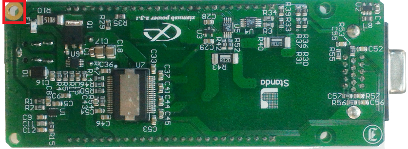
Top view of the controller board. A grounding terminal marked with the red square
Typical connection diagram for a controller (board, systems in box):
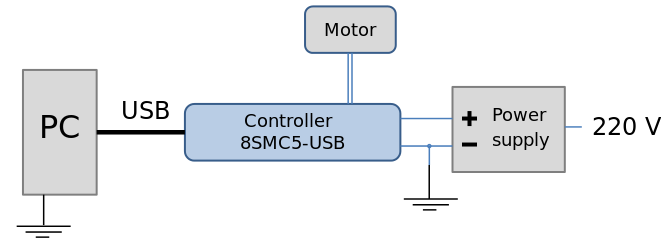
Controller grounded via minus electrode of power cable connection diagram
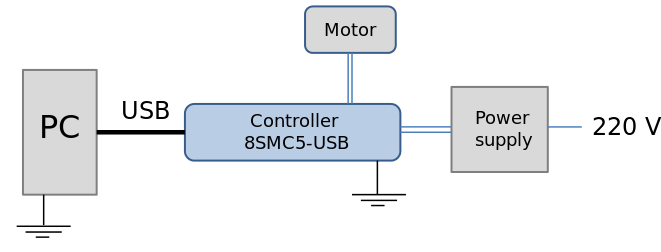
Controller connection diagram with grounding via special terminal
Warning
Power supply unit should be able to supply sufficient current to rotate the motor. As an absolute minimum it should be able to supply
where \(I_{power.min}\) is the minimum working current of
power supply unit,
\(I_{motor}\) is the operating current in the winding,
\(U_{power}\) is power supply unit stabilized voltage,
and \(U_{motor}\) is rated operating voltage of the motor.
It is recommended to use a power supply unit with operating
current equal to \(I_{power} \geq 2 * I_{power.min}\).
The \(U_{power}\) voltage should be greater than
\(U_{motor}\). The higher the voltage, the faster rotation
speed could be reached.
One can use power consumption of power supply unit to calculate minimum requirements instead. An absolute minimum of power is:
For example, for motor with operating winding current of 1 A and operating voltage of 5 V (with 5 W rated power consumption), the operating voltage of power supply unit may be chosen at 20 V with the output power of at least 10 W (the maximum operating current of power supply unit is at least 0.5 A).
2.2. Controller board
Important
It is strictly forbidden to touch the controller board
without any antistatic equipment. We
recommend you to use antistatic wrist strap.
You should not exceed maximum allowed voltage of
48V. If voltage goes over allowed value at more than 2 volts, it can
immediately and irreversibly damage the controller.
Important
It is strictly forbidden to connect positive wire of power supply to the controller board when ground wire is not connected. It is strictly forbidden to connect or disconnect power cable when the power supply is on, the controller is connected to the PC and the power supply and the PC are grounded. This may damage the PC! This is a common requirement for any electronic device with separate power source.
Warning
Before connecting the controller board to the motor or to the PC via USB interface, it is recommended to connect controller to power supply with proper grounding or to use separate grounding for controller with the specially marked ground terminal (look above).
2.3. One and two axis system in box
Important
You should not exceed maximum allowed voltage of 48V. If voltage goes over allowed value at more than 2 volts, it can immediately and irreversibly damage the controller.