4.1.1. Controller board
4.1.1.1. Dimensions and arrangement
Structurally the controller is designed as two boards, 127 x 46 x 32 mm each, rigidly connected to each other. A power part is mounted on the bottom board, the logic controller and control systems are located on the top board. A radiator at the power part is available.
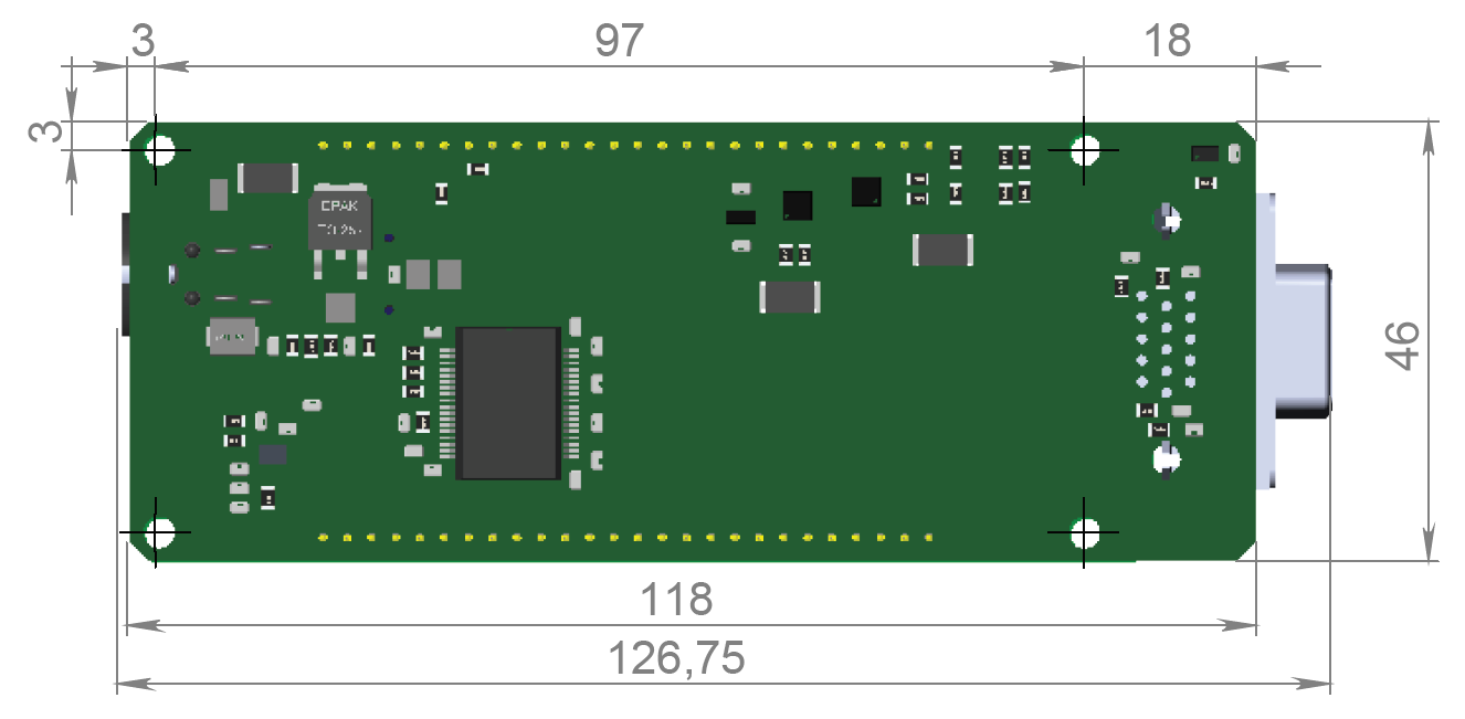
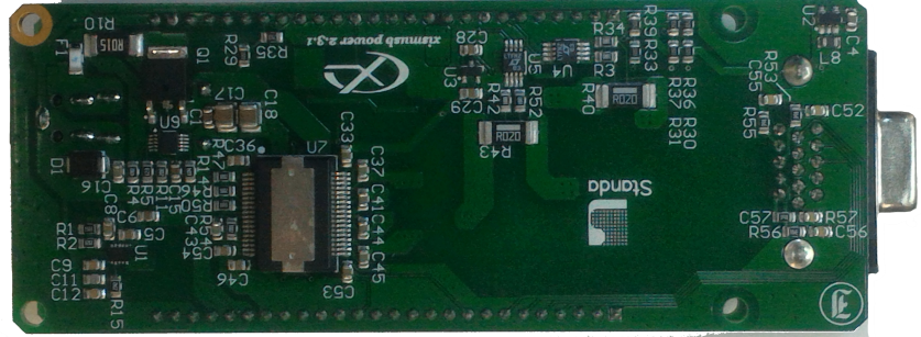
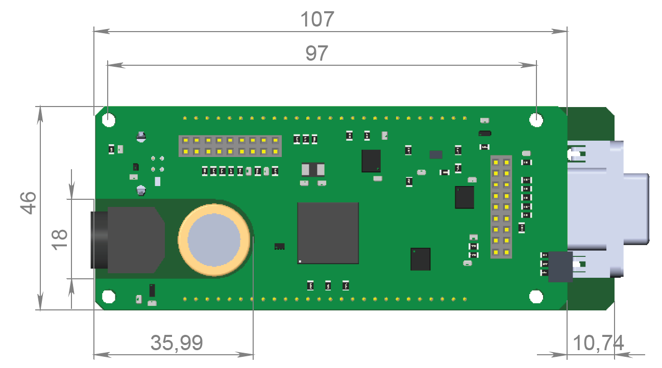
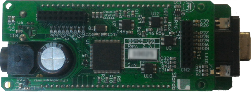
Bottom view on the controller. The view from power part and radiator side.
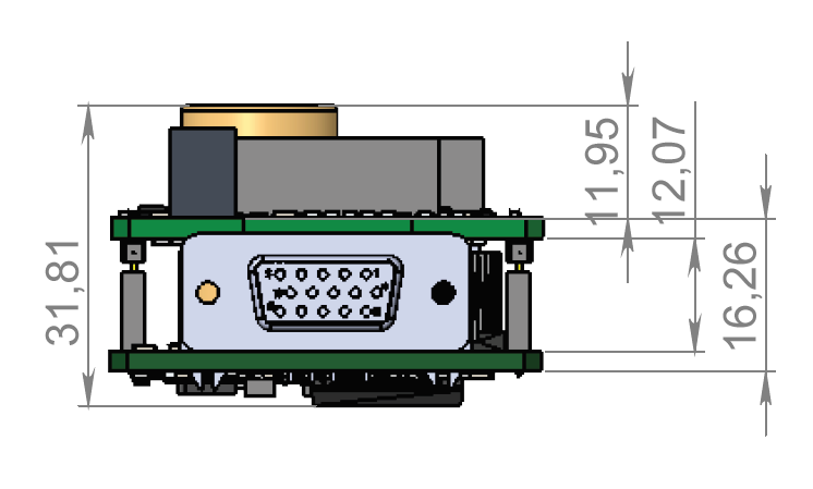
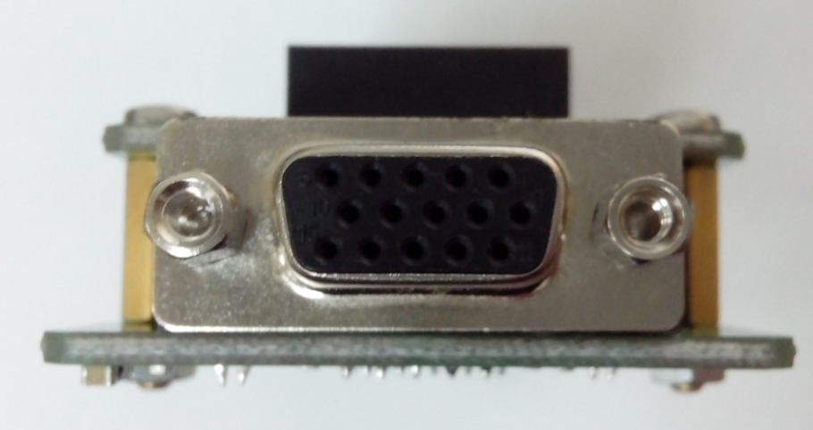
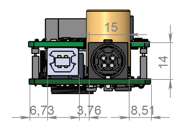
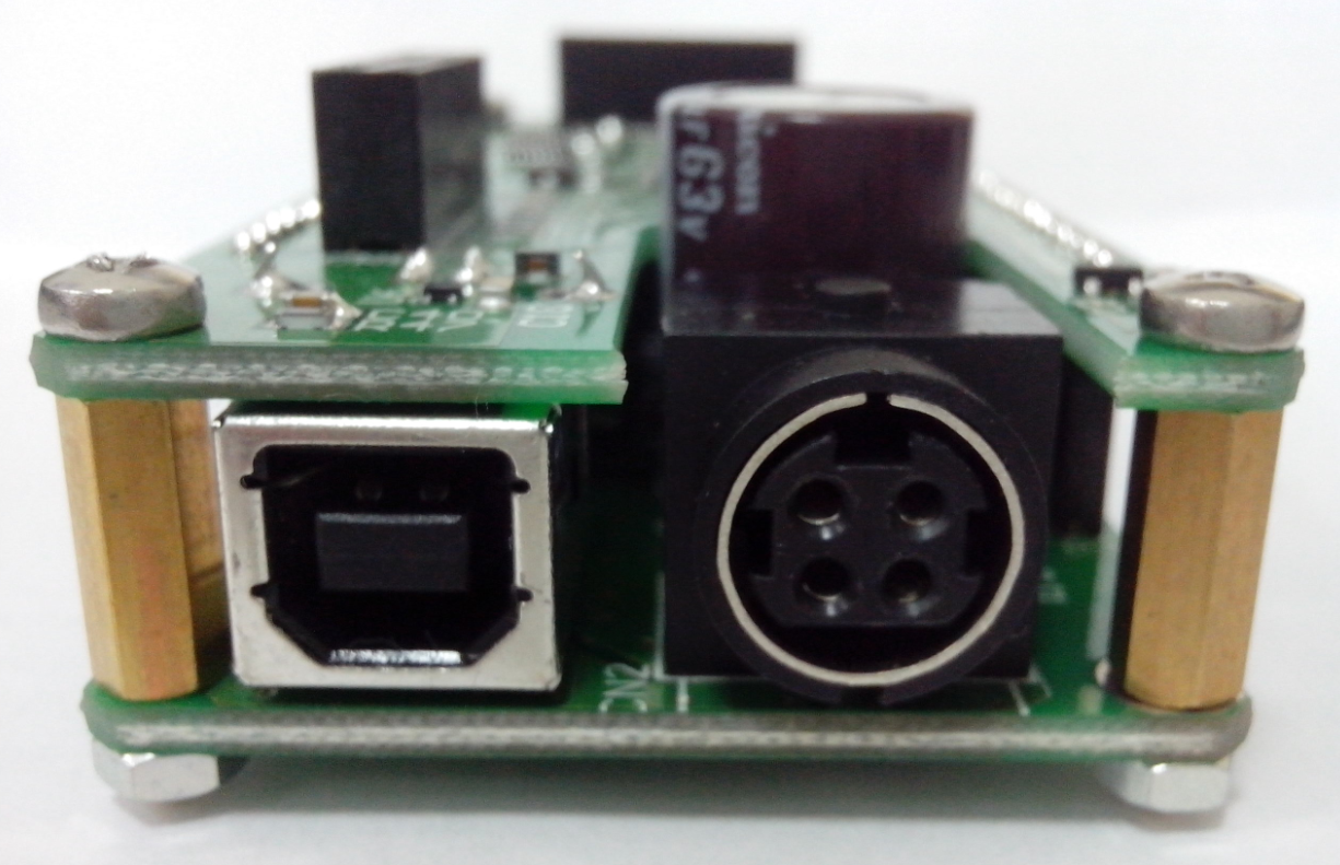
Front view on the controller. The view from stage cable side.
Rear view on the controller. The view from DIN and USB type-B connectors side.
Top view on the controller. The view from backplane connectors side.
Important
If you are mounting the radiator to the power part by yourself, please make sure that there is no contact between heat-conducting surfaces and conductive elements of the unit. Such contact may damage the power circuit! This warning is applicable only to controllers supplied without body.
4.1.1.2. Controller board connectors
4.1.1.2.1. Stage connector
A female DSub 15-pin connector for stage is mounted on the controller board.
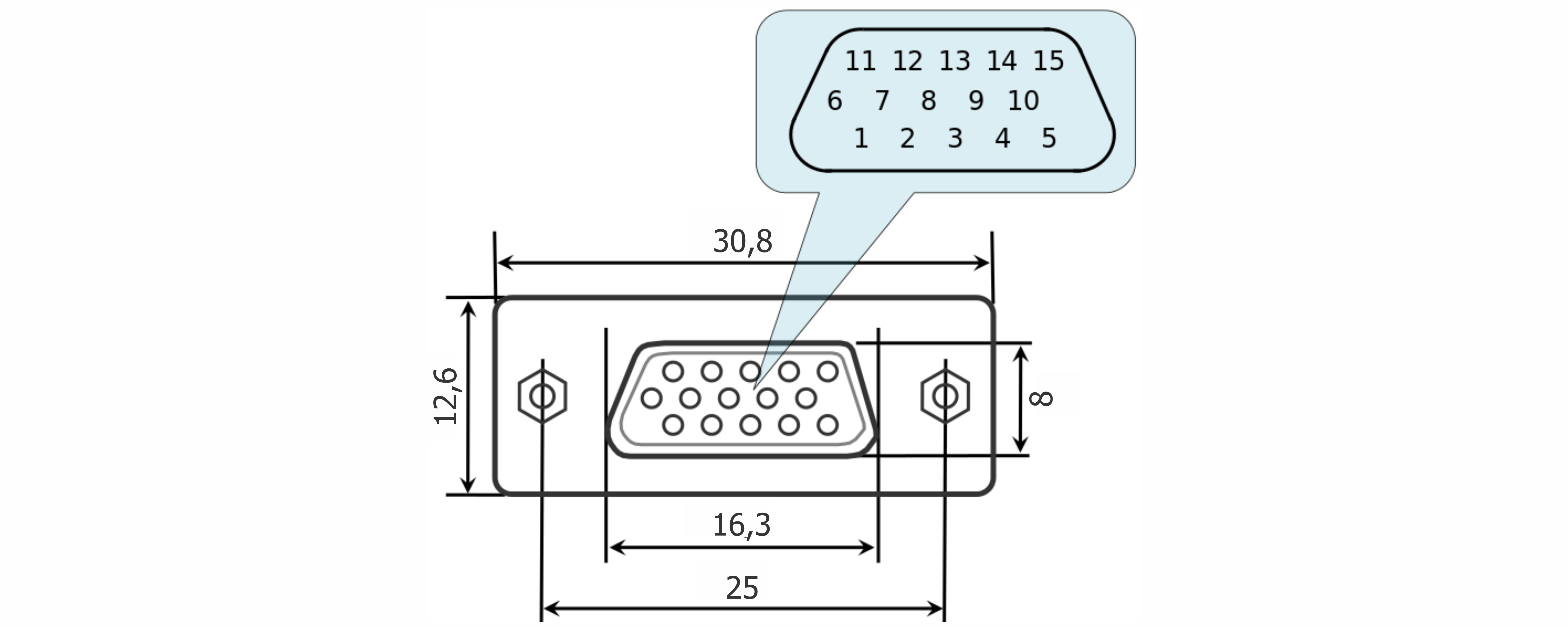
Dimensions and numbers of the pins in DSub connector (front view)
Pins functionality:
- Not phase B of SM or DC- of the motor
- Phase B of SM or DC+ of the motor or phase B on BLDC motor
- Not phase A of SM or DC- of the motor or phase C on BLDC motor
- Phase A of SM or DC+ of the motor or phase A on BLDC motor
- 5 V output, up to 500 mA - stabilized output for encoder power supply
- ID, one-wire interface for stage identification (only for Standa stages)
- Logic GND for limit switches, encoder, etc.
- 2nd limit switch
- 1st limit switch
- Encoder channel A
- Encoder channel B
- Revolution sensor input
- Inverted Encoder channel A
- Inverted Encoder channel B
- Inverted revolution sensor input
Note
Only firmwares 4.1.0 and newer support BLDC.
Note
Outputs 1 & 3 and 2 & 4 must be connected together for proper DC motor function if the nominal current of the motor is higher than 3A.
Warning
Plugging in/out the motor to the controller is not recommended while motor windings are under voltage.
4.1.1.2.2. Power supply connector
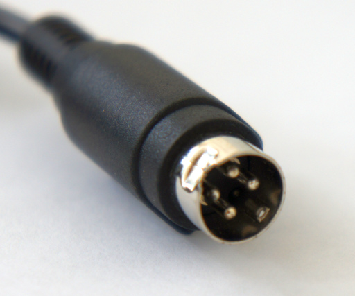
One and two-axis controller models use Kycon 4-pin DC power connector (part number KPPX-4P, www.kycon.com).
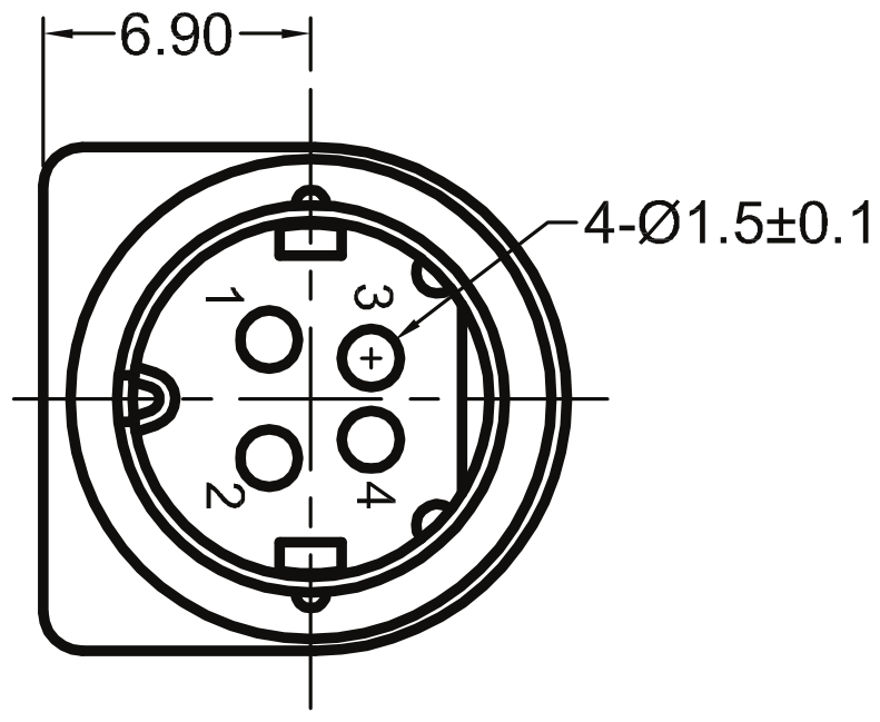
Pinout:
- Power, "-".
- Power, "+". 12-48V.
- Power, "-".
- Power, "+". 12-48V.
Important
Never supply the power to the controller and do not plug it to power connector if you are not confident that your power supply parameters conform to the requirements. Never attempt to plug the power supply to the controller if you are not sure power supply unit and controller connectors are compatible! The acceptable connection parameters are described in Safety instructions.
Important
Hot-swapping or unreliable connection of the power supply connector Kycon may damage the PC and/or the controller. For more details please refer to Safety instructions.
4.1.1.2.3. System control connectors
Controllers connect via connector USB type-B or Ethernet.
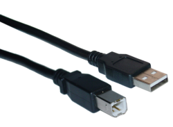
USB type-A - USB type-B cable
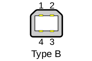
USB type-B connector
| Pin # | Name | Wire colour | Description |
|---|---|---|---|
| 1 | VCC | Red | +5 V DC |
| 2 | D- | White | Data - |
| 3 | D+ | Green | Data + |
| 4 | GND | Black | Ground |
Warning
Use verified USB cables only! Damaged or low-quality USB cable may cause improper controller operation, including motor rotation errors and errors of device recognition by PC operating system. Short cables with thick wires and screening are ideal for sustainable connection.
4.1.1.3. Backplane connector
A female 20-pin double-row connector (PBD-20R) with 2.54mm pitch is mounted on the controller board for backplane connection.
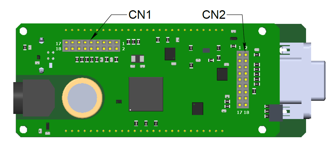
Dimensions and output pins numbers in BPC (BackPlane Connector), connector-side view
Pin function of CN1:
- Power GND 12-48 V
- JOY, an analog 0-3.3 V input used for external joystick connection
- Power GND 12-48 V
- POT, an analog 0-3.3 V input used for general purpose
- Power GND 12-48 V
- EXTGPIO0, a common input-output (or an Enable signal if an external driver is used), 3.3 V logic
- Power 12-48 V
- U_LED, a LED Status output displaying controller’s operating mode
- Power 12-48 V
- L_LIM, a LED output for left limit switch
- Power 12-48 V
- R_LIM, a LED output for right limit switch
- USB_SEL, selecting USB device in Multi-axis system
- EXTGPIO1, a common input-output, 3.3 V logic, up to 3 mA
- USB_D0_N, negative out of USB Slave
- H_USB_D0_N, negative out of USB Master
- USB_D0_P, positive out of USB Slave
- H_USB_D0_P, positive out of USB Master
Pin function of CN2:
- Reserved.
- RX1, serial port input, 3.3 V logic
- Reserved
- TX1, serial port input, 3.3 V logic
- Reserved
- DIR, a direction signal for external driver control, 3.3 V logic
- Reserved
- STEP, a step signal for external driver control, 3.3 V logic
- Reserved
- SYNC_OUT, synchronization output, 3.3 V logic
- Reserved
- SYNC_IN, synchronization input, 3.3 V logic
- EMBRAKE, an output for magnetic brake control, 3.3 V
- 3.3 V, up to 50 mA logic power (relevant for logic boards version 2.3.6 and newer)
- BUT_R, an external “Right” button
- +5 V output, up to 500 mA
- BUT_L, an external “Left” button
- Digital GND for 3.3 V and 5 V
Note
Reserved contacts of the internal connector do not require any additional connection or tightening to the ground/power supply. Just don’t use them.
Attention
A maximum designed operating voltage for Joy and Pot analog inputs is UP TO 3.3 V. Never supply these inputs with higher voltage, including 3.3 V value, otherwise the proper operation of all the analog channels of the controller may get disrupted and the controller itself or the motor may get damaged.
The outputs available at the internal connector are not protected. Mounting of any additional buffers or filtering chains is a total responsibility of user or developer who designs a backplane intended to use these lines.
While the controller is unpowered, no voltage over 0.3 V relative to the DGND pin is allowed on the internal connector. Provision of any additional protection preventing those accidents (if possible) is a total responsibility of user or developer who designs a backplane intended to use these lines.