4.5.4. Left-Right buttons control
For each system it is possible to control the movement of a motor with the buttons. Active button state is programmable and can be logical zero or one. Controller supports a 10-item speed array MaxSpeed[0-9], which is used both for joystick and button control.
The buttons control settings are red/written by commands SCTL/GCTL (set_control_settings/get_control_settings).
- If a left or right button is clicked then motor does a shift on an offset, specified by DeltaPosition and uDeltaPosition.
- If a left or right button is pressed and held for longer than MaxClickTime, then motor starts moving with MaxSpeed[0] and counting down to Timeout[0]. After Timeout[i] microseconds have elapsed speed is changed from MaxSpeed[i] to MaxSpeed[i+1] for any i between 0 and 9 (inclusive).
- If press the two buttons, the controller performs a stop with deceleration. Holding both buttons for 3 seconds starts the automatic calibration of the “home” position.
Note
You can fill only the upper part of the 10-item speed array if you don’t need all of them. Controller changes its speed to the next one only if the target speed is not zero and the timeout is not zero. For example, if MaxSpeed [0] and MaxSpeed[1] are nonzero and MaxSpeed[2] is zero (both step and microstep part), then the controller will start moving with MaxSpeed[0], then change its speed to MaxSpeed[1] after Timeout[0] and will keep moving with MaxSpeed[1] until the button is released. You can also set Timeout[1] to zero and leave MaxSpeed[2] set to any value to achieve the same result. Controller obeys its movement settings (with the exception of target speed). For example, when changing its speed from MaxSpeed[i] to MaxSpeed[i+i] controller will either accelerate with set acceleration value or change its speed instantly if acceleration is disabled.
The default state is set according to the voltage levels of the buttons (Output parameters). The state of each button can be software inverted. When active, the button is considered to be down. It does not matter how the condition is active (after changing the invert states, or when changing the voltage level at the physical impact of a button). The controller uses button contact debouncing. The button is considered pressed if active state lasts for longer than 3 ms.
| Type | TTL |
|---|---|
| Logic zero level | 0 V |
| Logic one level | 3.3 V |
Warning
When you turn on or reboot the controller at the input voltage level of the button is present, which is considered to be active, the controller will accept it as a button is pressed, and begin to obey the rules described above.
4.5.4.1. Connection diagram
4.5.4.1.1. Controller board
“Right” and “Left” control buttons can be connected to the controller board via BPC connector for a motor motion control.
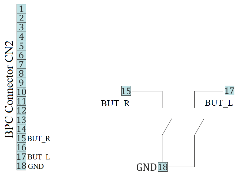
Scheme of buttons connection to the BPC connector
4.5.4.1.2. One-axis and two-axis systems
For controllers in case user buttons already placed on the front panel. However it is possible to connect custom buttons to the corresponding contacts that located on the D-SUB 9 pin connector and available only in two-axis system. Connection diagram is shown below.
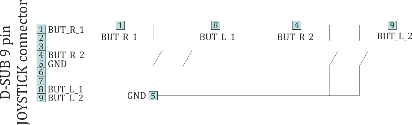
Scheme of buttons connection to the HDB-26 connector