4.5.3. Joystick control
4.5.3.1. General information
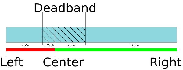
4.5.3.1.1. DeadZone
Controller accepts an input from an analog joystick with voltage in 0-3 V range. Voltage in the equilibrium (central) position and voltage in minimum and maximum position can be set to any value from the working range, if the following condition holds: minimum position < central position < maximum position. Controller uses digital representation of joystick input values: 0 V corresponds to a value of 0 and 3.3 V corresponds to a value of 10000.
Changing the DeadZone parameter is described in the Settings of external control devices.
To stop movement in the central position a DeadZone option is available, which is counted from the central position and measured in percent. Any joystick position inside DeadZone leads to the stopping of the movement by the controller. A larger than DeadZone deviation of the stick starts controller movement with the speed which is calculated from the deviation. The DeadZone ranges are illustrated on the following picture.
4.5.3.1.2. Joystick sensitivity
One can reverse the joystick with a reverse flag which can be useful to keep “right joystick offset means movement to the right” correspondence for any physical orientation of the joystick and the stage.
Movement speed has an exponential dependence on joystick deviation from the center. This enables one to reach high precision through small joystick shifts and high speed through large ones. Nonlinearity parameter (Exp factor) can be varied. If the nonlinearity parameter is zero, then the motor speed will linearly depend on joystick position.
The following graph shows dependence of movement speed on joystick position for the following settings:
| Central deviation | 4500 |
| Minimum deviation | 500 |
| Maximum deviation | 9500 |
| Dead zone | \(10\%\) |
| Maximum movement speed | 100 |
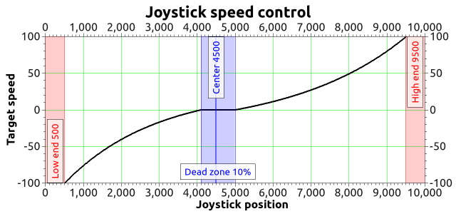
An example of motion speed dependence on joystick deviation
4.5.3.1.3. Speed control using the buttons
Sometimes exponential joystick response which combines high accuracy and high speed is not enough. That’s why controller supports maximum speed table. User can switch between these speeds using Left-Right buttons control.
In joystick mode, the buttons control the speed of movement. That is, using the buttons, you can increase or decrease the speed corresponding to a certain deviation of the joystick.
A table of MaxSpeed[i] speeds corresponding to 100% deviation of the joystick is recorded in the controller’s memory. When pressing the “right” button, the speed corresponding to 100% deviation changes from MaxSpeed[i] to MaxSpeed[i+1]. When the “left” button is pressed, the maximum speed changes from MaxSpeed[i] to MaxSpeed[i-1]. When the controller starts, i=0. The number of speeds in the table is 10. If MaxSpeed[x] is zero (integer and fractional parts), then you cannot switch to this speed from MaxSpeed[x1]. This is done to be able to limit the table to a smaller number of speeds. An attempt to go beyond the limits of the index of the velocity table (0-9) also does not lead to anything.
Setting the MaxSpeed[i] values is described in the Settings of external control devices.
The buttons do not adjust the absolute speed, but a coefficient linking the deviation of the joystick with the speed of movement. Therefore, with zero deviation of the joystick (or rather, when the joystick is in the dead zone), it will be impossible to set the motor in motion using the buttons alone.
Controller has contact debouncing on control buttons. For keypress to register button press should last longer than 3 ms.
If joystick sits within dead zone for more than 5 seconds it will be logically considered to be out of DeadZone only when it has been physically out of DeadZone for more than 100 ms. This allows user to release joystick and to be confident that even occasional noise on joystick output won’t lead to unnecessary motor motion. While joystick is within Dead zone the controller can receive any commands from computer including motion commands, home position calibration commands, etc. If during command execution joystick is brought of Dead zone the motion command is canceled and motor is switched to joystick control. This allows the user to turn on joystick control mode and use it only when necessary.
Everything that is related to movement under the control of controller commands is also applicable to joystick movement. This includes acceleration, maximum speed limit, windings poweroff delay, magnetic brake, backlash compensation, etc. For example, if you suddenly release joystick handle and let it return into the DeadZone, then, if corresponding modes are on, controller will gradually slow the motor, make a backlash compensation motion, stop the motor, fix the motor shaft with the magnetic brake, smoothly reduce current and switch off windings power.
Important
In Joystick control mode, the physical and virtual buttons remain in working order
Warning
Do not disconnect or connect the joystick to the switched on controller!
When disconnecting/connecting the joystick to the enabled controller,
the joystick or controller will not burn, but the stages connected to the
controller will start moving to the limit switches.
4.5.3.2. Connection diagram
Important
Analog inputs for joystick connection are designed for a range of 0-3.3 V. Be careful and do not exceed voltage for joystick contacts.
4.5.3.2.1. Controller board
A contact for joystick control is located on the BPC connector.
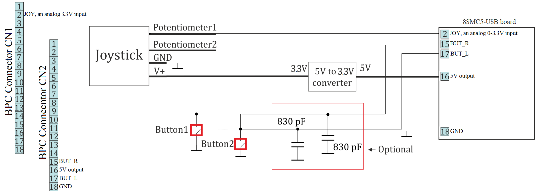
Connection of joystick to the controller board via BPC connector
4.5.3.2.2. One-axis and two-axis systems
Joystick connector is available only in two-axis system. A connection diagram is shown below.
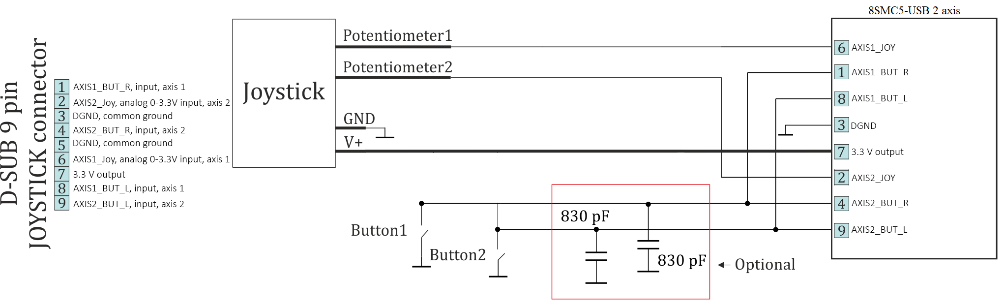
Connection of joystick to the two-axis system via D-SUB 9 pin connector