4.5.9. External driver control interface
Interface allows to control any external driver with a help of 3 standard signals: enable, direction, clock. This mode is convenient when controller power capability is not enough but it is desirable to use its capabilities such as limit switches, revolution sensor, position control, scripting language, multi-axis systems, joystick/button control, magnetic brake, etc. For example, for creation of multi-axis system with one powerful lifting axis which is controlled by external controller and two less powerful horizontal axes, you can use XiLab with 3-axis interface and its scripts and also synchronize the motion of all three axes. I.e. external driver replaces only power part of the controller.
Important
External driver mode works only for stepper motors and only in “None” mode (xilab settings/Stepper motor tab/Feedback None)
In any other modes or with any other type of motor, the External driver mode will not work!
Clock signal defines the quantity of signals in the given Direction (logical one to the right, logical zero to the left). Displacement is a minimum step in the current settings of step division. For step division 1/32 there will be 32 impulses per one step. Don’t forget to set external driver in such a way that it would use the same step division.
Warning
Clock signal frequency in the given controller is limited by 78 kHz. That’s why to reach necessary speed one might need to reduce step division. Foe example, if rotation speed of 4000 steps per seconds is needed it is necessary to use 1/8 step division or less.
| Type | TTL |
| Logical zero level | 0 V |
| Logical one level | 3.3 V |
4.5.9.1. Connection diagram
Warning
Outputs for external driver control are not sufficiently protected and can be damaged in case of incorrect usage. Proper connection and necessary electric protections are a responsibility of an engineer who designs drivers’ connection system.
4.5.9.1.1. Controller board
For external driver connection three outputs in BPC connector are used.
Warning
Pin 13 is the general purpose input/output (see General purpose digital input-output (EXTIO)), but it loses its functionality when external driver control is enabled.
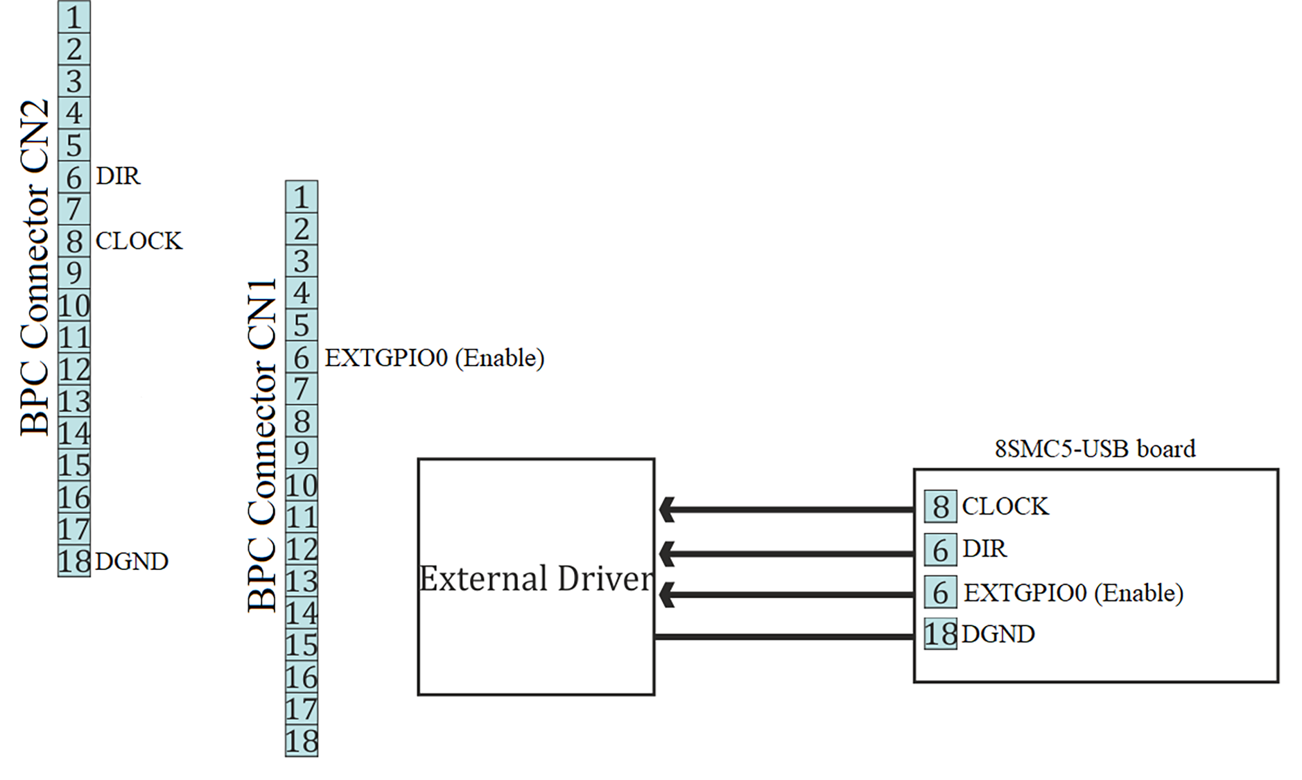
Scheme of connection to the external driver for the controller board
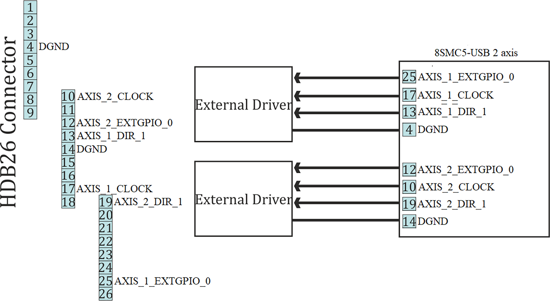
4.5.9.1.2. One-axis and two-axis systems
Only two-axis system has the external driver interface. It outputs on the HDB-26 connector.
Warning
Pins 12 and 25 are general purpose inputs/outputs (see General purpose digital input-output (EXTIO)), but they loses functionality when external driver control is enabled.