4.5.5. TTL synchronization
4.5.5.1. Principle of operation
TTL-synchronization is used to synchronize controller motion with external devices and/or events. For example, the controller can output synchronization pulse each time it moves a certain distance. Vice versa, controller can shift a certain distance on incoming synchronization pulse, for example from an experimental setup which is ready to move to the next measurement position.
To use mechanical contacts as an input synchronization signal a contact debouncing is provided. One can set minimum input pulse length which is recognized as a valid synchronization signal. An active state is a logical one (see Input parameters), and a raising edge is considered to be the start of a signal. However, if for some reason this is undesirable, both options may be inverted independently.
| Type | TTL |
|---|---|
| Logic zero level | 0 V |
| Logic one level | 3.3 V |
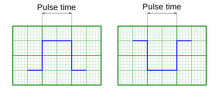
Inversion of input and output syncronization pulse illustrated
Note
If simultaneous start of several controllers in a multi-axis system is desirable, minimum input pulse length should be the same for all controllers. Contact debouncing should not be used in systems with no mechanical contacts and short noise pulses in synchronization input channel. One should use an RC-circuit which would filter these noise pulses instead.
Synchronization is important in multi-axis systems because it allows one to simultaneous movement on multiple axes. To do this all axes are prepared to start the movement, all slave axes are configured to start moving on input synchronization pulse, one master axis is set to output a synchronization pulse on the start of the movement. Master axis output is connected to slave axes’ input. In this setup any movement of the master axis triggers to immediate response of all connected axes.
Note
One should set minimum input sync pulse length to 0 if this kind of connection is used. This disables contact debouncing, but since there are no mechanical contacts it is not needed. If minimum input sync pulse length is not zero then to avoid desynchronization of master and slave axes one should set input sync pulse length the same for all controllers, connect syncout to both master and slave inputs and issue start command by activating input manually.
Synchronization input and output are independent from each other and other means of motion control. Control through XiLab application or any other user application, joystick control and left-right buttons control are independent of input/output synchronization state. Last command always takes priority. For example, a movement command sent from XiLab will cancel current movement which happened because of input sync pulse, but will not affect output sync state. Next input sync pulse will cancel current movement initiated by user program and will replace it with movement command according to sync in settings.
Note
Sync in settings may be saved in controller flash (non-volatile) memory. In this case everything related to synchronization may also be said about autonomous controller operation. For example, you may set up shift on offset on syncin pulse with syncout pulse on movement stop and connect the controller to a standalone measurement device, which starts measurements on its own input sync pulse and outputs a sync pulse on measurement end. Then you can run such a system without a PC, because after the first sync pulse all measurements and movements will happen automatically.
4.5.5.2. Connection
The controller is supplied with two TTL-sync channels on the BPC connector.
4.5.5.3. Sync in
Synchronization input has a setting, which defines minimum syncin pulse length which may be registered. This length is measured in microseconds. Use this setting to decrease controller sensitivity to noise. Synchronization input may be turned on or off. If it is on, then a sync in pulse will lead to a situation as if Predefined displacement mode command has taken place, which takes its Position and Speed from syncin settings. If syncin settings are changed during the time the movement takes place it will not change current movement parameters. Movement parameters will change on the next front on syncronization input. This designed deliberately to allow one to set up next shift parameters in multi-axis systems during movement.
Warning
When you turn on or reboot the controller at the input voltage level of the synchronize input is present, which is considered to be active, the controller interprets it as if Predefined displacement mode command has taken place.
Note
Position and Speed are two separate variables which also may be saved in non-volatilve controller memory. They are used only with synchronization input.
Note
Syncin movement obeys acceleration, max speed settings and all other settings which are related to motion. Their incorrect setting may disrupt coordinated movement in multi-axis system.
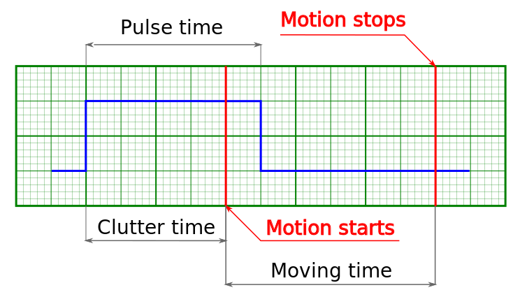
Movement starts because input pulse is longer than debounce time
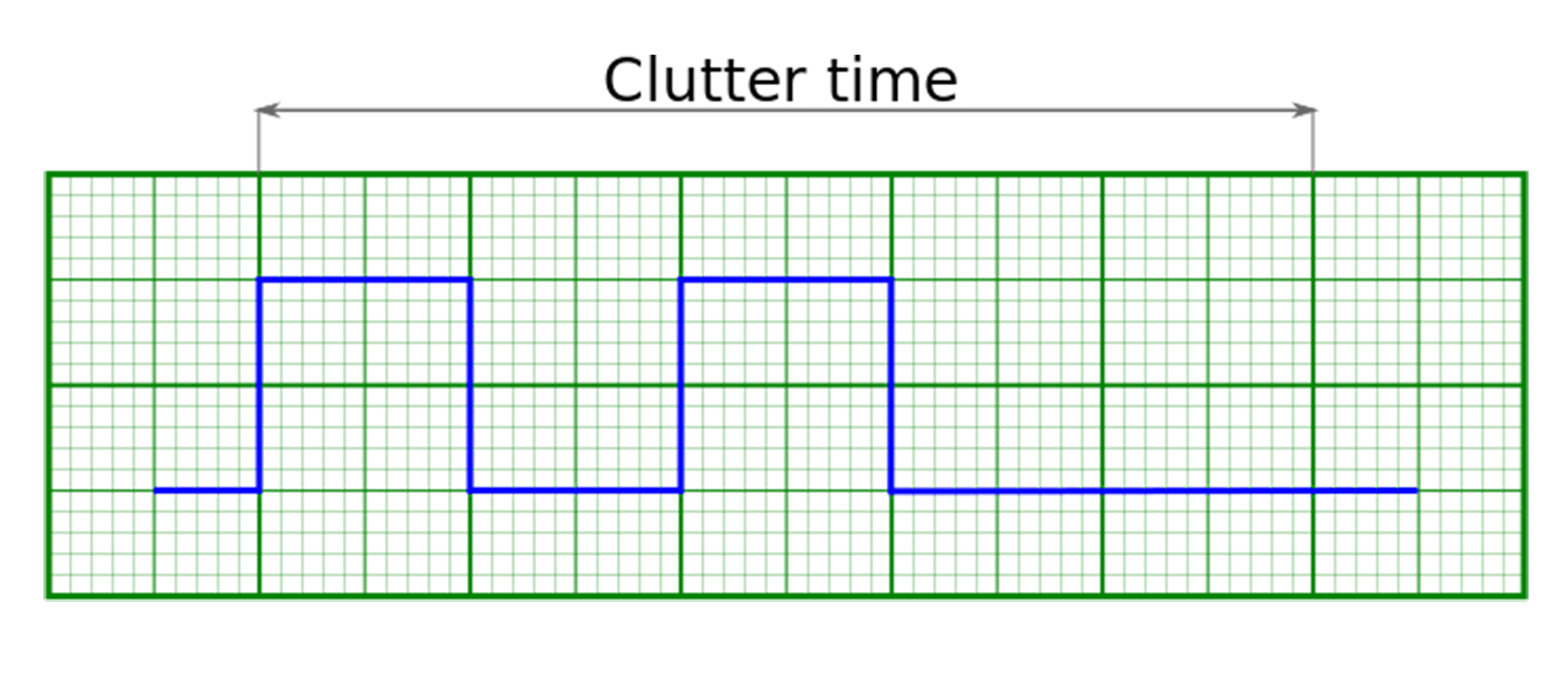
Movement does not start because input pulses are shorter than debounce time
Warning
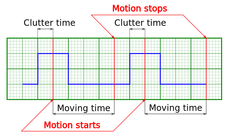
If a second syncin pulse is received while controller is still moving then the end position will be offset by two times the shift distance from the start, if a third pulse is received, then by three times, etc.
One-time movement with double shift length because second syncin pulse came in before the end of the movement
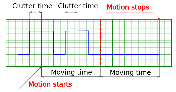
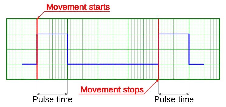
Two separate shifts with two start and two stop phases
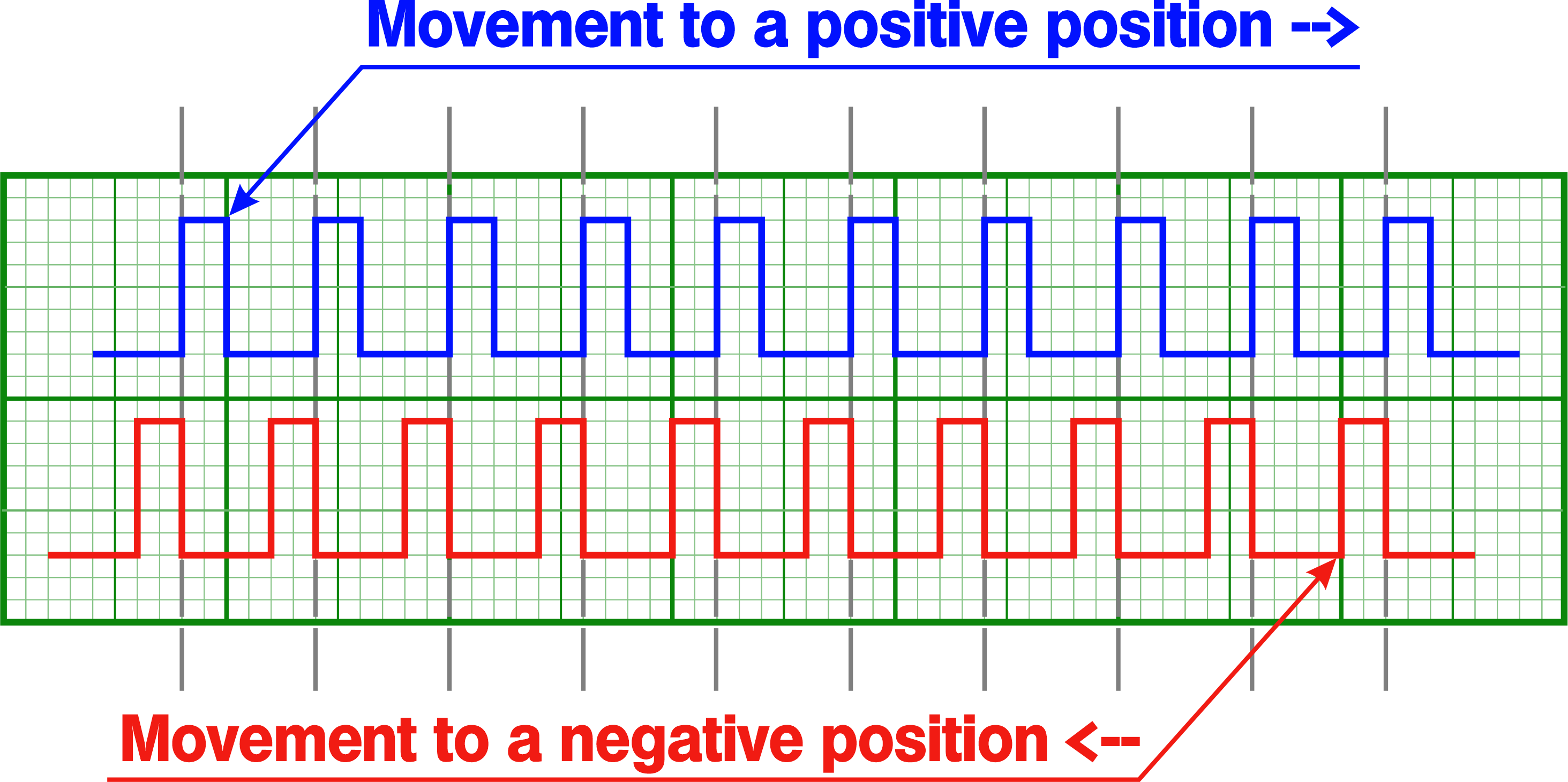
Default setting is active state is one, movement on raising edge. Synchronization input may be inverted to the active state is zero, movement on trailing edge.
Note
Inverted synchronization input setting will lead to the change in the definition of active/inactive state which may be seen, for example, in controller status. However, programmatical inversion of the syncin state by itself will not lead to the start of the movement, even if the transition happened into the active state.
4.5.5.4. Sync out
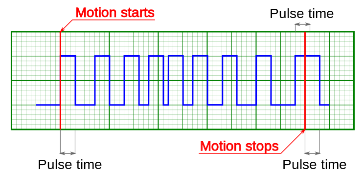
Output synchronization is used to control external devices tied to controller movement events. Sync out pulse can be emitted on start and/or stop of the movement, and/or on each shift on the preset distance. ImpulseTime setting defines the length of sync pulse, either in microseconds or in distance units. Synchronization output can be switched into general purpose digital output mode. In this mode it is possible to set zero/one output logic level programmatically.
Sync out pulses generated on start and stop of the movement (fixed length pulse)
Note
If syncout pulse length is measured in distance units and, for example, is equal to 10 stepper motor steps and “syncout pulse on stop” mode is active, then the active state on synchronization output will be set on the movement end, but will be cleared only when the motor will move 10 more steps during the next movement.

Syncout pulses generated on start and stop of the movement (pulse is measured in distance units)
Note
If you wish to reconfigure synchronization output and are not sure which state is it in, change its state to general purpose output and set the desired logic level.
Sync out pulses on movement with acceleration and “generate on shift” mode (pulse length measured in distance units)
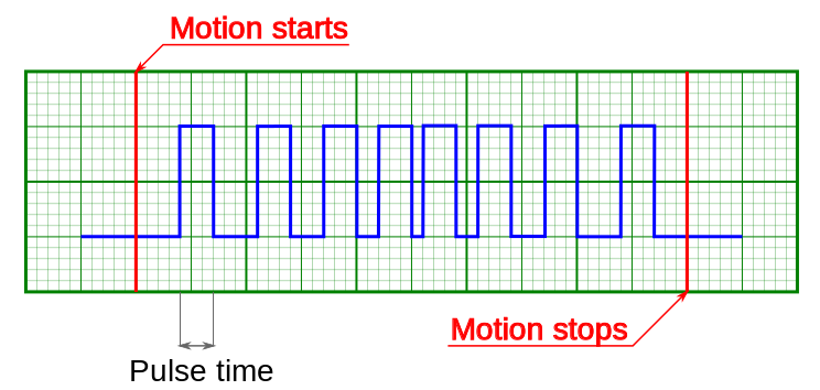
Sync out pulses on movement with acceleration and “generate on shift” mode (pulse length measured in microseconds)
Note
Periodic syncout pulse generation imitates revolution sensor with reducing gear. Coordinates which trigger syncout pulse generation are counted from zero position and not from the position the controller is in at the start of the movement. For example, if synchronization output is set up to generate pulses every 1000 steps then pulses will be generated in positions 0, 1000, 2000, 3000, etc. Pulse generation works when moving in both directions. Pulse is generated when the quotient of current coordinate and pulse generation period changes. That is, pulse is generated when position 1000 is reached when moving in the direction of increasing position and it is generated when position 1000 is left when moving in the direction of decreasing position. Also, syncout pulse is always generated when position 0 is reached from any direction (including the case when position is reset by the ZERO button).
Note
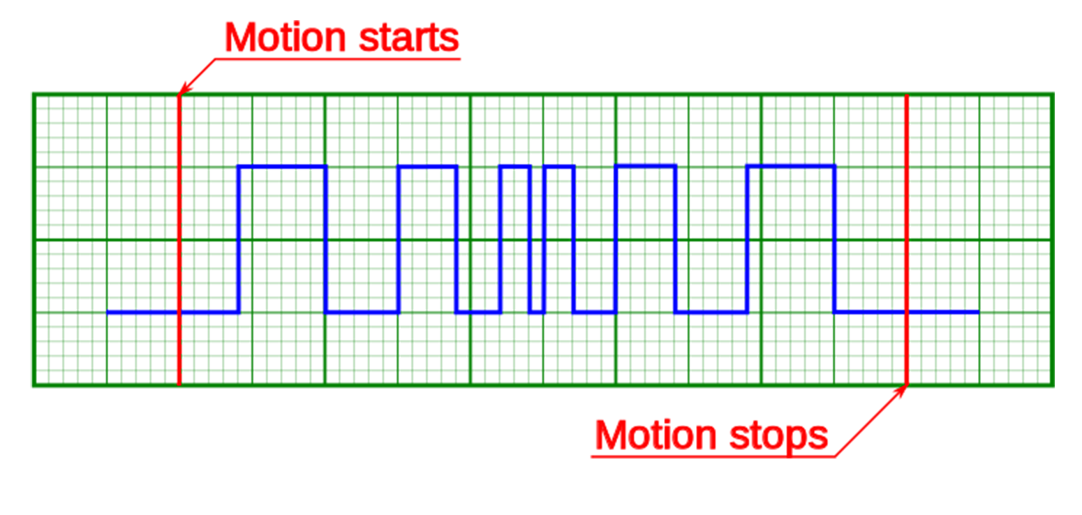
Whenever syncout pulses overlap they are merged into one pulse.
Syncout pulse merge illustrated, pulse generation on start, stop and shift on offset (pulse length measured in microseconds)
The controller will set virtual marks with a specified step that corresponds to the value of the “Every” field starting from zero. The synchronization pulse is always generated after passing the next mark. Therefore, the position of the pulses depends on the direction of movement:
- When moving in a positive direction (position increases, pulses are generated in the direction of movement), that is, they grade the position of the mark
- When moving in a negative direction (position decreases, pulses are generated in the direction of movement), that is, they are smaller than the position of the mark
Example:
Pulse width: 100
Every flag: 1000
The controller will set virtual marks:
…, -2000, 1000, 0, 1000, 2000, …
- When moving from -1500 to 1500, the output will be a logical unit when passing the following coordinate ranges:
[-1000, -900], [0, 100], [1000, 1100] - When moving in the opposite direction from 1500 to -1500 logical unit when passing the following coordinate ranges:
[1000, 900], [0, -100], [-1000, -1100]
Important
With short movements within the pulse duration around the mark, the output state may not return to zero, so as not to create unnecessary noise switching. The “Every” flag was not designed for single shifts, it was created to generate pulses over long distances
The absolute error of the pulse duration is ±25 microseconds. If you set the pulse duration to 30 microseconds, then the actual pulse duration will vary from about 5 microseconds to 55 microseconds. The error value does not depend on the pulse duration. Therefore, the relative error for longer pulses will be much smaller.
Synchronization settings setup in XiLab is described in Synchronization settings section.
4.5.5.5. Connection diagram
4.5.5.5.1. Controller board
Controller board contains two TTL-channels of synchronization on the BPC connector.
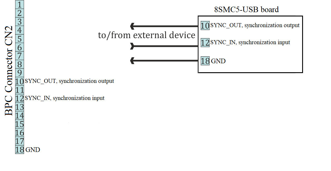
Scheme of connection to the synchronization channels for the controller board
4.5.5.5.2. One-axis and two-axis systems
Synchronization signals on the one-axis and two-axis systems are located on the HDB-26 connector.
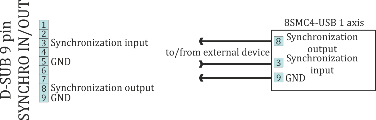
Scheme of connection to the synchronization channels for the one-axis system
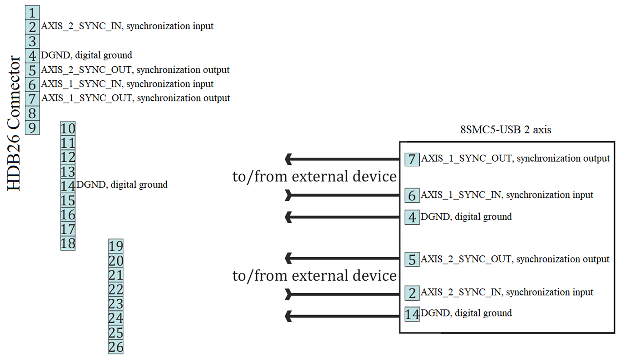
Scheme of connection to the synchronization channels for the two-axis system