4.5.2. Operations with magnetic brake
There is an output pin on BPC connector for magnetic brake control, which is installed on the stepper motor shaft. Magnetic brake is used hold motor position in unpowered state.
4.5.2.1. Description of operation
Magnetic brake consists of a magnet and a spring, which performs stops the motor shaft. In case there is no voltage applied to the magnet the spring clamps the shaft in place which allows to keep motor position. When voltage is applied the spring releases the shaft.
4.5.2.1.1. Controller operating sequence during stage shutdown.
Motor shutdown (the time of shutdown is recorded in controller) -> magnet power supply cut off, shaft fixation -> board power supply cut off
During power-on the sequence is reversed.
Since any movement has inertia, the following parameters are set to control magnetic brake and the position fixation process:
- Time between motor power on and brake off (ms)
- Time between brake off and readiness to move (ms)
- Time between motor stop and brake on (ms)
- Time between brake on and motor power off (ms)
If magnetic brake function is turned off then controller will constantly transmit brake release signal. This allows to move engine equipped with magnetic brake without rotor fixation during pauses. If winding poweroff function is turned off then controller will only pause between brake switching and movement start/stop.
All magnetic brake settings can be changed online and brake will be switched to the mode which would be active in case if the setting would have a new value. For example a large increase of brake activation delay when the brake is already active will lead to brake deactivation and countdown to the new delay value. It is also possible to turn on or off magnetic brake itself or winding power function.
| Type | TTL |
| Brake is released | 3.3 V |
| Brake is clamped | 0 V |
| Operational current | no more than 4 mA |
Magnetic brake setting in XIlab program is described in Brake settings section.
4.5.2.2. Magnetic brake connection diagram
In order to use magnetic brake check if your controller system is equipped with a special converter board. Models which meets this demands can be identified by letters BR in its title, for example 8SMC5-USB-B8-1BR.
Contact pin responsible for magnetic brake control in boxed versions of controller is located on the Supplementary one-axis system connector. A connection diagram is shown below.
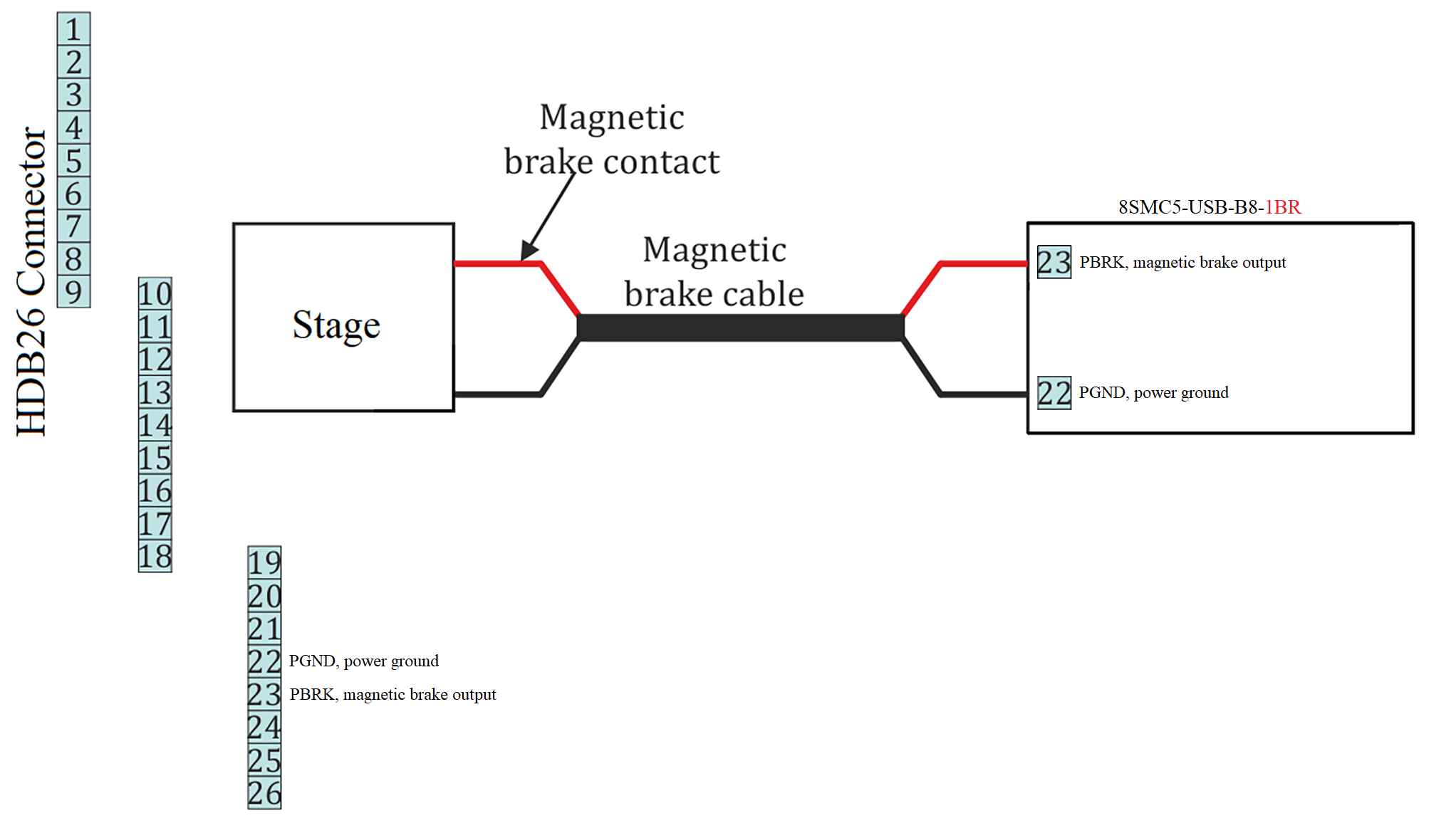
Connection of magnetic brake to one-axis system
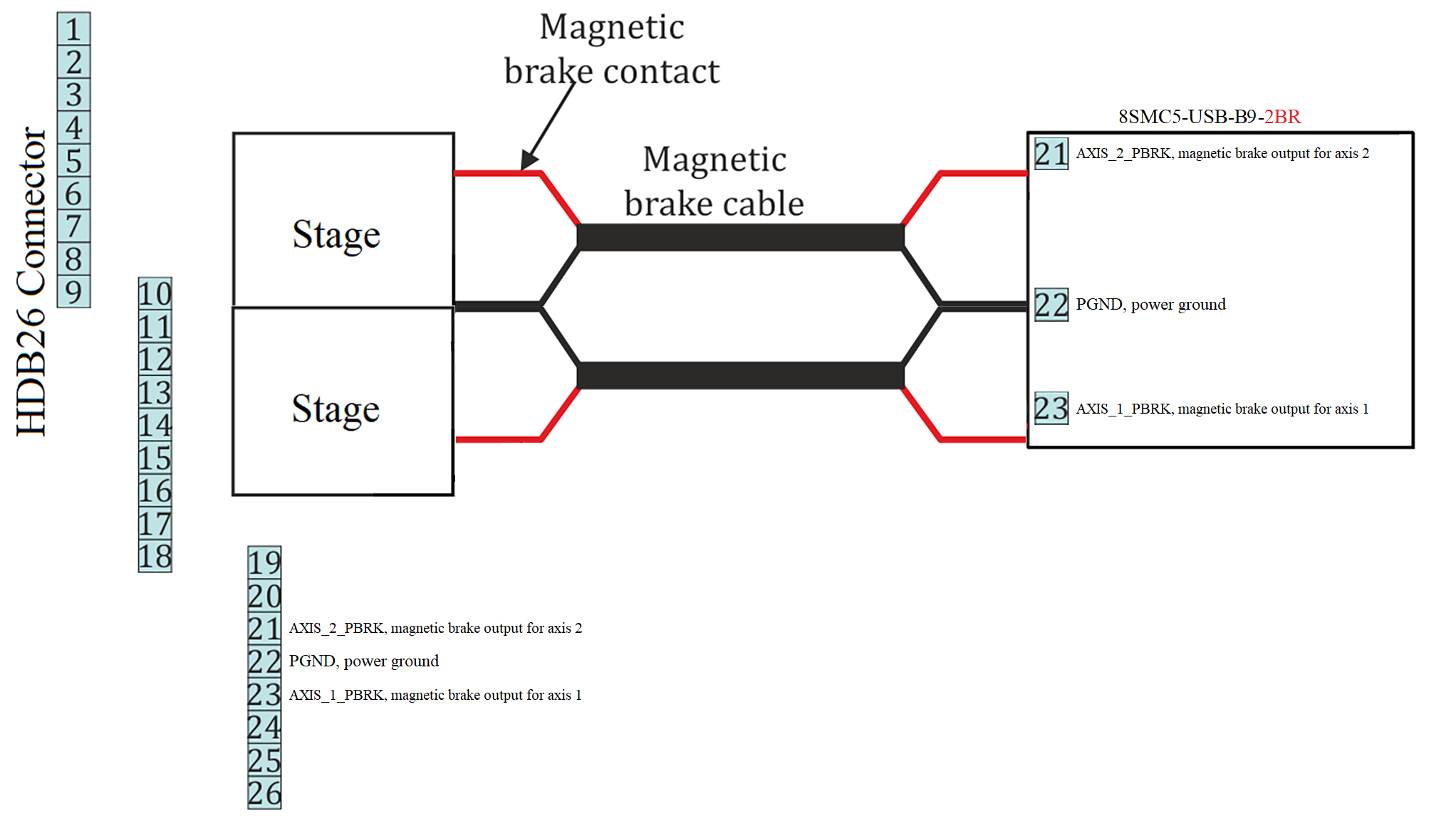
Connection of magnetic brake to two-axis system
Important
It is guaranteed that the magnetic brake will work from Power supply PS36-4.4-4