4.5.6. Multi-axis system design
Controller axes in multi-axis systems are identified by the controller serial number. Each controller has its own unique serial number, which may be seen in XiLab software on About controller page. One can read controller serial number using get_serial_number function (see Programming guide).
Multi-axis systems based on this controller are assembled using an active backplane based on a USB-hub or an external USB-hub.
Important
It is recommended to base backplanes on a USB-hub with galvanic isolation from the PC and an additional power supply or a 36 V -> 5 V converter, because this provides higher noise immunity and guarantees sufficient 5 V power.
For proper multi-axis system functioning one should first connect all controllers to the power and USB connectors (place controllers on the backplane).
Then, in any order, do all of the following:
- Connect power to the backplane
- Connect external devices
- Connect master controller to the USB
Note
Note. Additional 5 V power supply requirements: output current no less than 250 mA per axis, 400 mA per axis for full functionality.
Multi-axis connection diagram implies connecting power supply to pins 1 and 2 of the BPC connector and connecting data lines D-/D+ from the USB hub to pins 3 and 4 of the BPC connector.
Power is connected next:
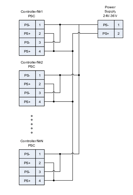
Controller connection diagram in multi-axis configuration
PSC - Power Supply Connector, used to connect power supply to the controller
BPC - Back Panel Connector, used to connect accessories to the controller