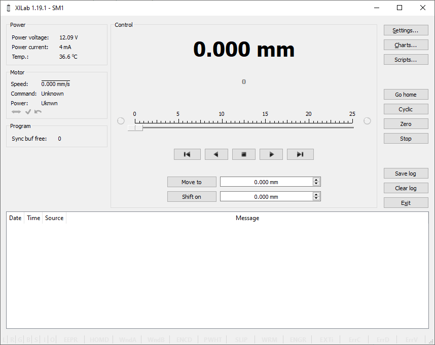
5.2.2. XILab Main window in single-axis control mode
XILab Main Window in General Motor mode
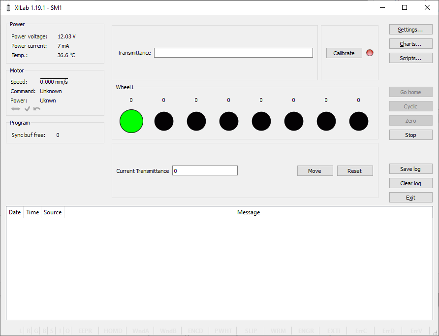
XILab Main Window in Attenuator mode
In the left part of the window in Power and Motor groups of parameters status of the controller and the motor is available. In the central part of the window there is the Control group, containing the elements of motor motion control. On the right there is a group of buttons to control the application as a whole. At the bottom there is a log, which is hidden as the window is resized to its minimum size and a status bar. Below we consider these groups in more detail.
5.2.2.1. Motion Control Unit
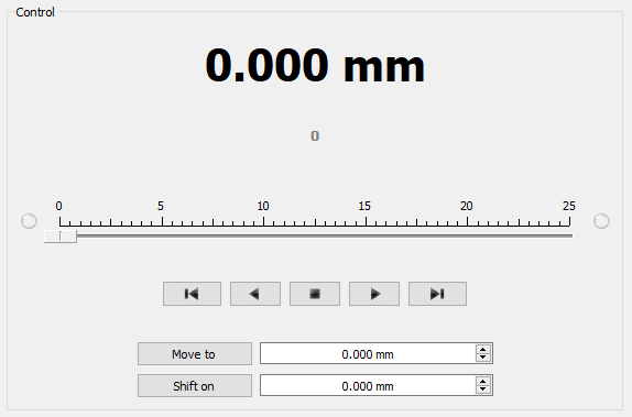
Control Unit
In the central part of the block there is an indicator of the current position. Below it, in case the encoder is enabled, is located an encoder position indicator. In the closed loop mode (see Operation with encoders section) the main and the secondary indicators swap their places.
Below is the Control unit, containing the elements of motor motion control. Let us examine them in greater detail:
5.2.2.1.1. Movement without specifying the final position

Movement control buttons
- The buttons Left, Stop and Right trigger movement to the left without specifying the final position, stop with deceleration any previously started movement, and start the movement to the right without specifying the final position, respectively.
- Button Left to the border will make the motor rotate to the left border of the slider. Right to the border, respectively, will do it to the right edge of the slider.
- When you press and hold the keyboard buttons Right or Left and the slider block has input focus, the movement starts in the direction of increasing or decreasing coordinate. When you release the button the movement stop as if the Stop button on the main window have been pressed.
5.2.2.1.2. Movement to the target point
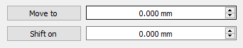
Movement control to the given point
- Move to button starts the process of moving to the given position.
- Shift on button starts the process of shift to a given distance from the target position.
5.2.2.1.3. Target position for motion commands
Commands Move to and Shift on use the target position to calculate the movement. The target position is changed by the following commands:
Commands Stop, Left, Right, Left up to the border and Right up to the border do not alter the target position.
5.2.2.2. Attenuator Control Unit
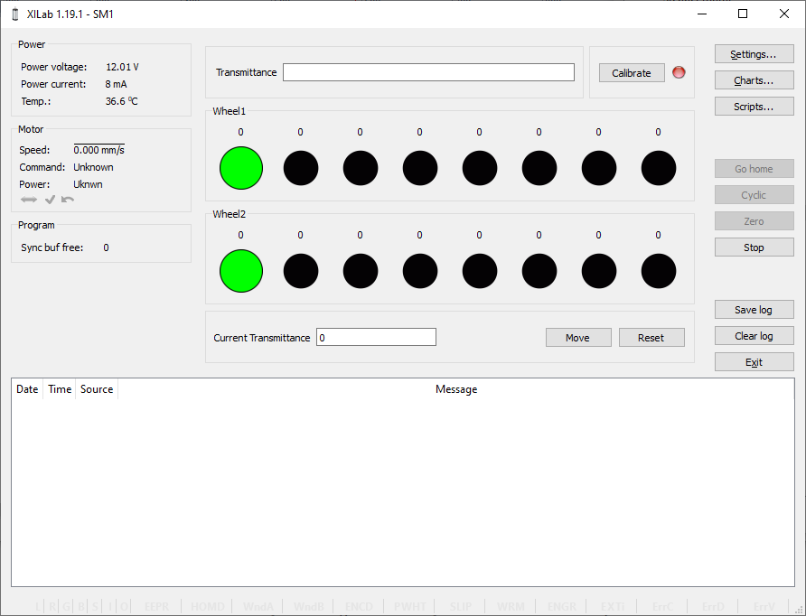
Attenuator Control Unit
At the top of the attenuator control block a Transmittance window and a Calibrate button are located. Transmittance window contains a control to select desired transmittance coefficient. Calibrate button does manual calibration, or location of the initial position, of the attenuator - first it initiates one revolution of attenuator with current controller settings to determine relative position of attenuator wheels and then does Automatic Home position calibration. * Calibrate* button is optional - if the attenuator did not perform the calibration or it was reset, for example by pressing Cancel during movement, calibration will be performed before the next movement automatically.
Attenuator has one or two wheels, each wheel contains 8 optical filters. Below these filters are visualized as bars with circles. Below a Current Transmittance window is located. This window contains trasmittance coefficient which is the closest to desired one that can be achieved with the current filters.
Move button performs movement toward the filters corresponding to the Current Transmittance, that is, the highlighted ones.
Reset button deactivates all filters.
5.2.2.3. Controller and motor status
5.2.2.3.1. Controller Power Supply
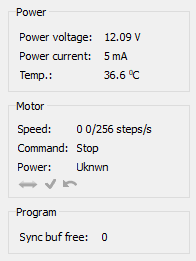
Power group of parameters contains the following indicators:
- Power voltage - voltage supplied to the power module.
- Power current - current consumption of the power module.
- Temp. - Temperature of the controller processor.
If the color of the indicator Power voltage changes to red, it shows that voltage power supply exceeds the allowed value range over the acceptable value. In this case, the controller switches to Alarm state. You can change this parameter in the section Critical board ratings.
A horizontal bar above the field Power voltage indicates that the power voltage exceeds the motor max voltage, you can change this parameter in the section Settings of kinematics (DC motor).
If color of the indicator Power current turns red, it shows that the current consumed by the controller from the power supply is over the acceptable value. In this case, the controller switches to Alarm state. You can change this parameter in the section Critical board ratings.
A horizontal bar above the field Power current indicates that the power current exceeds the motor max current, you can change this parameter in the section Settings of kinematics (DC motor).
If the color of the indicator Temp turns red, it shows that the temperature of the controller board exceeds the acceptable value. In this case, the controller switches to Alarm state. You can change this parameter in the section Critical board ratings.
Important
It is possible to quit the Alarm state after terminating of the events that caused Alarm, provided that the flag Sticky Alarm is not set. If the flag Sticky Alarm is on, use the Stop button to quit the Alarm state.
5.2.2.3.2. Motor status
Motor group of parameters contains the following indicators:
- Speed - rotation speed of the motor.
- Command - the last performing (bold font) or executed (plain font)
controller command. Controller command
appears in black if the flag of the
motion error MVCMD_ERROR is not set, in red otherwise. Can be one of
the following options:
- Move to position - move to the set position
- Shift on offset - offset for a predetermined distance
- Move left - move left
- Move right - move right
- Stop - stop
- Homing - find the home position
- Loft - backlash compensation
- Soft stop - smooth stop
- Unknown - unknown command (it may appear immediately after the controller starts)
- Power - state of stepper motor power supply. Can be one of the
following options:
- Off - motor winding is disconnected and not controlled by the driver,
- Short - winding is short-circuited through the driver,
- Norm - winding is powered with nominal current,
- Reduc - winding is deliberately powered with reduced current relatively to operational one to reduce the power consumption,
- Max - winding is powered with maximum available current, which a scheme with a given voltage supply can output.
Note
You can use the GPIO flag to detect the connected stage
A horizontal bar above the Speed parameter indicates that the speed has reached the maximum speed, which is defined in the Settings of kinematics (DC motor).
5.2.2.3.3. Program status
Program group of parameters contains the following indicators:
- Sync buf free - free slots in the SyncIn command buffer (this function have been disabled for the moment).
5.2.2.4. Group of application control buttons
- Settings… button opens controller settings, see Application settings.
- Chart… button opens a window with charts, see Charts.
- Scripting… button opens scripting window, see Scripts.
- Go home button searches for the home position, see Home position settings.
- Cyclic button turns on the cyclic motion, see Cyclical motion settings.
Note
The Cyclic command is a constituent command: when invoking Cyclic in XiLab at the controller level the sequence of Move to commands is executed.
- Zero button resets the current position of the motor and the encoder value.
- Stop button sends the command of immediate stop, resets the Alarm state, clears the command buffer for synchronous motion and stops a script if it is running.
- Save log button saves the contents of the log to a file in CSV format (opens a file selection dialog window).
- Clear log button clears the contents of the log.
- Exit button performs safe shutdown, see Correct shutdown.
5.2.2.5. Status bar
Status bar contains current controller status indicators. From left to right these are 7 flags,
- L - Left button state
- R - Right button state
- G - State of external GPIO pin
- B - State of brake pin
- S - State or revolution sensor pin
- I - State of sync in pin
- O - State of sync out pin
and separate indicators (flags)
- EEPR - Lights up green when the stage is equipped with EEPROM memory chip.
The built-in stage profile is uploaded from the EEPROM memory chip if the EEPROM_PRECEDENCE flag (XILab Settings->About device tab) is enabled, allowing you to connect various stages to the controller with automatic setup. - HOMD - Lights up after successful execution of home() command meaning that relative position scale is calibrated against a hardware absolute position sensor like a limit switch. Drops after loss of calibration like harsh stop and possibly skipped steps.
- WndA/WndB has 1 of 4 statuses:
- Winding A/B is disconnected.
- Winding A/B state is unknown.
- Winding A/B is short-circuited.
- Winding A/B is connected and working properly.
Important
Status is determined using statistical data while moving, taking its time, and turning this status rather useless in common applications. Therefore this function have been disabled for the moment.
- ENCD - Encoder state has 1 of 5 statuses:
- Encoder is absent.
- Encoder state is unknown.
- Encoder is connected and malfunctioning.
- Encoder is connected and operational but counts in other direction.
- Encoder is connected and working properly. - PWHT - Power driver overheat.
Motor control is disabled until some cooldown. This should not happen in boxed versions of controller. This may happen in bare board version of controller with a custom radiator. Redesign your radiator then. - SLIP - Motor slip detected.
Flag is set when encoder position and step position are too far apart. You can disable the “Position control” flag or increase the error in the “threshold” field on the XILab Settings->Position control tab to stop these error from happening.
Important
The ENCD flag is only active in the None and EMF modes. In other modes, such as Encoder and Encoder Mediated, it is not used, as these modes cannot operate without an encoder.
After the controller is powered on, the flag will be in the unknown state - a movement is required to determine the position. As the movement occurs, the flag’s value may change.
- WRM - Lights up when there is a substantial difference between stepper motor windings resistances.
This usually happens with a damaged stepper motor with partially short-circuited windings. You can diagnose the problem according to the instructions in our manual
Important
The WRM algorithm was not originally designed to be used for belt-driven stages (for example, 8MRB450-350 or 8MRB240-152) due to the fact that the belt can stretch and vibrate. Vibration usually occurs at high speeds, which knocks down the work of the WRM algorithm. For belt drive stages, this is normal behavior
- ENGR - Lights up red when the motor control error occurs.
Motor control algorithm failure means that it can’t define the correct decisions with the feedback data it receives. Single failure may be caused by mechanical problem. A repeating failure can be caused by incorrect motor settings. - EXTI - The error is caused by the external EXTIO input signal set to cause this error in the settings (XILab Settings->EXTIO tab)
- ErrC - Command error encountered.
The command received is not in the list of controller known commands. Most possible reason is the outdated firmware that can be updated in XILab Settings->About device tab->Autoupdate button. - ErrD - Data integrity error encountered.
The data inside command and its CRC code do not correspond, therefore data can’t be considered valid. This error may be caused by EMI in UART/RS232 interface. - ErrV - Value error encountered.
The values in the command can’t be applied without correction because they fall out the valid range. Corrected values were used instead of the orginal ones. - Ctbl - Loading correction table status. The flag lights up green when the correction table is loaded and applied for a stage.