4.3.5. Operation with encoders
4.3.5.1. Application of encoders
Encoders are designed to provide accurate and fast position feedback.The feedback is performed by the motor shaft position, by stage’s linear position, by the motorized table rotation angle or by any other parameter related to the shaft position and measured by using the two-channel quadrature encoder complying the requirements described in Specifications chapter for the appropriate controller type. Controller 8SMC5 supports differential encoders and simple (single-ended) encoders.
Warning
Auto-detect works only with 3.3 V and 5 V (with error 0.2 V) encoders.
4.3.5.2. What is quadrature encoder?
Encoder is a mechanical motion sensor. The quadrature encoder is designed for direct detection of the shaft position. The sensor transmits the relative shaft position by using two electric signals at CH A and CH B channels shifted relative to each other at 1/4 of period.
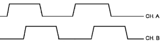
The signals at CH A and CH B outputs of quadrature encoder
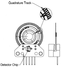
An optical quadrature encoder mechanics
An optical quadrature encoder mechanics is shown at the figure above. There are two optocouplers used. The operational principle of an optocoupler is as following: a LED and a detector are arranged opposite to each other from different sides of a disc. The optocoupler opens when disc’s “window” coincides with the detector (the outgoing signal is logic zero). The outgoing signal is logic one if the detector is closed by opaque part of the disc.
Number of steps per revolution (CPR) is the main parameter of the quadrature encoder. The standard resolution values for encoder are from 24 to 1024 CPR. Each period of signal alteration is interpreted by 1, 2 or 4 codes which is corresponding to X1, X2 and X4 operating modes. This controller uses the most accurate X4 mode. The maximum pulse frequency of the single-ended encoder is 200 kHz and for a differential encoder it is 5 MHz. The maximum frequency of each encoder’s signal depends on the applied encoder itself, since for 200 kHz in X4 mode the controller can read up to 800,000 encoder counts per second. For a frequency of 5 MHz in X4 mode, the controller can read up to 20 million encoder counts per second.
4.3.5.3. Controllers features
There are two operating modes with encoder available for the controller:
- the encoder is used as the main position sensor (this is the main operating mode for DC motors and the optional one for stepper motors).
- slippage, backlash or steps loss detection (the recommended mode for joint operations with stepper motors, in case the encoder is not used as a primary position sensor, see more).
4.3.5.4. Encoder connection
The encoder is connected to the controller via D-SUB 15 pin connector, which is in all systems (controller board, one-axis and two-axis in box)
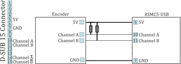
The diagram of single-ended encoder connection using D-SUB 15 pin connector.
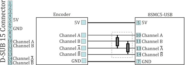
The diagram of differential encoder connection using D-SUB 15 pin connector.
See also the Example of a motor connection chapter.
Warning
Encoder inputs of the controller internally pulled up to logic one by using the 5.1kΩ resistors. Frequently encoder outputs are of “open collector” type equipped with internal pull-up resistor. During the data transmission they provide good characteristics while passing from higher logic level to lower. However, the pass from logic 0 to logic 1 is more graduate. It passes through the RC circuit formed by pull-up resistor and cable capacitance. This is the most important thing if the cable is long (up to 5 meters). If the internal pull-up is not sufficient, the pull-up resistor with r=1.5kΩ may be added for every +5 V to each output in order to improve the transmission speed parameters; before doing that please check if the open collector of the encoder can transmit 5mA current. The resistors insertion diagram is shown above. The maximum operating speed for quadrature encoder may be increased by adding a push-pull driver with the outgoing current over 10mA to its output, providing quick 0 - 1 and 1 - 0 transmission edges.
4.3.5.4.1. Operation with long cables
For correct encoder operations on cables longer than 5 meters, it is recommended to use an encoder with a differential output (RS485) to reduce the effect of electromagnetic interference. When using the RS485, all differential pairs must be terminated with a 120 Ohms resistor in the connector to the controller.
The cable must have an additional internal shield for digital signals (pins 5-15) connected to the DGND (pin 7) on the controller side and on the stage side. The external shield must be connected directly to the connector metal case on the stage side and to the connector metal case through a 47 nF capacitor on the controller side.
4.3.5.4.2. Automatic encoder type detection
Important
On 8SMC5 controllers with hardware revisions 2.3.1 and 2.3.3, the encoder autodetect feature is not supported. Starting from hardware revision 2.3.5 and newer, this feature operates correctly.
The controller hardware version can be found in XILab, on the About device tab, in the Hardware version field.
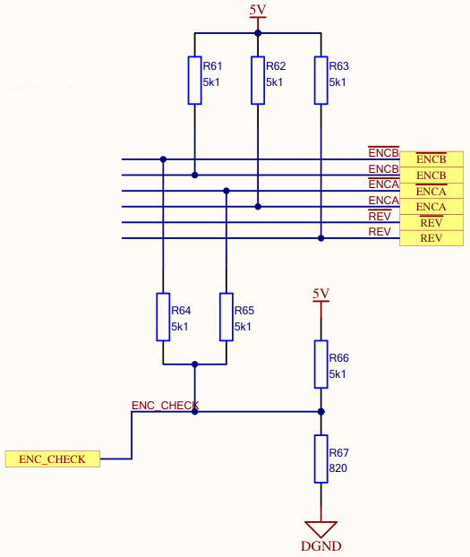
The Autodetect function of the encoder type checks the state of the “not ENCA” and “not ENCB” inputs. These inputs can be in a disconnected state, or in a logical low or high state. If both inputs are disconnected (a single-ended encoder is connected), then the voltage at the ENC_CHECK output will be 0.69 V. If at least one signal line has a logical low or high state, the voltage will be different (see the table):
| notENCB | notENCA | Output | Voltage |
|---|---|---|---|
| 0.0 | 0.0 | – | 0.542328 |
| 0.0 | 5.0 | – | 1.084656 |
| 0.0 | NaN | – | 0.608309 |
| 5.0 | 0.0 | – | 1.084656 |
| 5.0 | 5.0 | – | 1.626984 |
| 5.0 | NaN | – | 1.216617 |
| NaN | 0.0 | – | 0.608309 |
| NaN | 5.0 | – | 1.216617 |
| NaN | NaN | – | 0.692568 |
Thus, the closest voltage values for a differential encoder are: 0.61 V and 1.08 V for an encoder with 5 V signals, and 0.61 V and 0.90 V for an encoder with 3.3 V signals. The controller checks whether the measured voltage falls within the 0.66 V – 0.83 V range. If the value falls within this range 5 times in a row within 500 ms, the encoder type is set to single-ended. If the value does not fall into this range 5 times within 500 ms, the encoder type is set to differential.
The autodet mechanism of the encoder type does not depend on the connection of the REV signal and is generally reliable. Failures of the algorithm are only possible when both a terminating resistor is used in the cable and the encoder driver is too weak, causing the “not ENCA” and “not ENCB” signal voltages to drop to 3 V.
In case of problems with automatic encoder type selection, encoder type can be selected manually in the feedback settings.