6.2. Communication protocol specification
Communication protocol v18.3
- Protocol description
- Command execution
- Controller-side error processing
- Library-side error processing
- Controller error response types
- All controller commands
- Command GACC
- Command GBRK
- Command GCAL
- Command GCTL
- Command GCTP
- Command GEDS
- Command GEIO
- Command GENG
- Command GENI
- Command GENS
- Command GENT
- Command GFBS
- Command GGRI
- Command GGRS
- Command GHOM
- Command GHSI
- Command GHSS
- Command GJOY
- Command GMOV
- Command GMTI
- Command GMTS
- Command GNME
- Command GNMF
- Command GNVM
- Command GPID
- Command GPWR
- Command GSEC
- Command GSNI
- Command GSNO
- Command GSTI
- Command GSTS
- Command GURT
- Command SACC
- Command SBRK
- Command SCAL
- Command SCTL
- Command SCTP
- Command SEDS
- Command SEIO
- Command SENG
- Command SENI
- Command SENS
- Command SENT
- Command SFBS
- Command SGRI
- Command SGRS
- Command SHOM
- Command SHSI
- Command SHSS
- Command SJOY
- Command SMOV
- Command SMTI
- Command SMTS
- Command SNME
- Command SNMF
- Command SNVM
- Command SPID
- Command SPWR
- Command SSEC
- Command SSNI
- Command SSNO
- Command SSTI
- Command SSTS
- Command SURT
- Command ASIA
- Command CLFR
- Command CONN
- Command DBGR
- Command DBGW
- Command DISC
- Command EERD
- Command EESV
- Command GBLV
- Command GETC
- Command GETI
- Command GETM
- Command GETS
- Command GFWV
- Command GOFW
- Command GPOS
- Command GSER
- Command GUID
- Command HASF
- Command HOME
- Command IRND
- Command LEFT
- Command LOFT
- Command MOVE
- Command MOVR
- Command PWOF
- Command RDAN
- Command READ
- Command RERS
- Command REST
- Command RIGT
- Command SARS
- Command SAVE
- Command SPOS
- Command SSER
- Command SSTP
- Command STMS
- Command STOP
- Command UPDF
- Command WDAT
- Command WKEY
- Command ZERO
6.2.1. Protocol description
Controller can be controlled from the PC using serial connection (COM-port). COM-port parameters are fixed controller-side:
- Speed: 115200 baud
- Frame size: 8 bits
- Stop-bits: 2 bits
- Parity: none
- Flow control: none
- Byte receive timeout: 400 ms
- Bit order: little endian
- Byte order: little endian
6.2.2. Command execution
All data transfers are initiated by the PC, meaning that the controller waits for incoming commands and replies accordingly. Each command is followed by the controller response, with rare exceptions of some service commands. One should not send another command without waiting for the previous command answer.
Commands are split into service, general control and general information types. Commands are executed immediately. Parameters which are set by Sxxx commands are applied no later than 1ms after acknowledgement. Command processing does not affect real-time engine control (PWM, encoder readout, etc).
Both controller and PC have an IO buffer. Received commands and command data are processed once and then removed from buffer. Each command consists of 4-byte identifier and optionally a data section followed by its 2-byte CRC. Data can be transmitted in both directions, from PC to the controller and vice versa. Command is scheduled for execution if it is a legitimate command and (in case of data) if its CRC matches. After processing a correct command controller replies with 4 bytes - the name of processed command, followed by data and its 2-byte CRC, if the command is supposed to return data.
6.2.3. Controller-side error processing
6.2.3.1. Wrong command or data
If the controller receives a command that cannot be interpreted as a legitimate command, then controller ignores this command, replies with an “errc” string and sets “command error” flag in the current status data structure. If the unreconized command contained additional data, then it can be interpreted as new command(s). In this case resynchronization is required.
If the controller receives a valid command with data and its CRC doesn’t match the CRC computed by the controller, then controller ignores this command, replies with an “errd” string and sets “data error” flag in the current status data structure. In this case synchronization is not needed.
6.2.3.2. CRC calculation
CRC-16/MODBUS is calculated for data only, 4-byte command identifier is not included. CRC algorithm in C is as follows:
unsigned short CRC16(INT8U *pbuf, unsigned short n)
{
  unsigned short crc, i, j, carry_flag, a;
  crc = 0xffff;
  for(i = 0; i < n; i++)
  {
    crc = crc ^ pbuf[i];
    for(j = 0; j < 8; j++)
    {
      a = crc;
      carry_flag = a & 0x0001;
      crc = crc >> 1;
      if ( carry_flag == 1 ) crc = crc ^ 0xa001;
    }
  }
  return crc;
}
This function receives a pointer to the data array, pbuf, and data length in bytes, n. It returns a two byte CRC code.
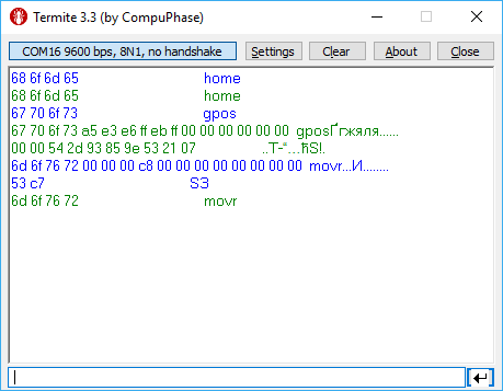
The example of CRC calculation:
Command code (CMD): “home” or 0x656D6F68
0x68 0x6F 0x6D 0x65
CMD
Command code (CMD): “gpos” or 0x736F7067
0x67 0x70 0x6F 0x73
CMD
Command code (CMD): “movr” or 0x72766F6D
0x6D 0x6F 0x76 0x72  0x00 0x00 0x00 0xC8  0x00 0x00  0x00 0x00 0x00 0x00 0x00 0x00  0x53 0xc7
CMD                  DeltaPosition        uDPos      Reserved                       CRC
6.2.3.3. Transmission errors
Most probable transmission errors are missing, extra or altered byte. In usual settings transmission errors happen rarely, if at all.
Frequent errors are possible when using low-quality or broken USB-cable or board interconnection cable. Protocol is not designed for use in noisy environments and in rare cases an error may match a valid command code and get executed.
6.2.3.3.1. Missing byte, controller side
A missing byte on the controller side leads to a timeout on the PC side. Command is considered to be sent unsuccessfully by the PC. Synchronization is momentarily disrupted and restored after a timeout.
6.2.3.3.2. Missing byte, PC side
A missing byte on the PC side leads to a timeout on PC side. Synchronization is maintained.
6.2.3.3.3. Extra byte, controller side
An extra byte received by the controller leads to one or several “errc” or “errd” responses. Command is considered to be sent unsuccessfully by the PC. Receive buffer may also contain one or several “errc” or “errd” responses. Synchronization is disrupted.
6.2.3.3.4. Extra byte, PC side
An extra byte received by the PC leads to an incorrectly interpreted command or CRC and an extra byte in the receive buffer. Synchronization is disrupted.
6.2.3.3.5. Altered byte, controller side
An altered byte received by the controller leads to one or several “errc” or “errd” responses. Command is considered to be sent unsuccessfully by the PC. Receive buffer may also contain one or several “errc” or “errd” responses. Synchronization can rarely be disrupted, but is generally maintained.
6.2.3.3.6. Altered byte, PC side
An altered byte received by the PC leads to an incorrectly interpreted command or CRC. Synchronization is maintained.
6.2.3.4. Timeout resynchronization
If during packet reception next byte wait time exceeds timeout value, then partially received command is ignored and receive buffer is cleared. Controller timeout should be less than PC timeout, taking into account time it takes to transmit the data.
6.2.3.5. Zero byte resynchronization
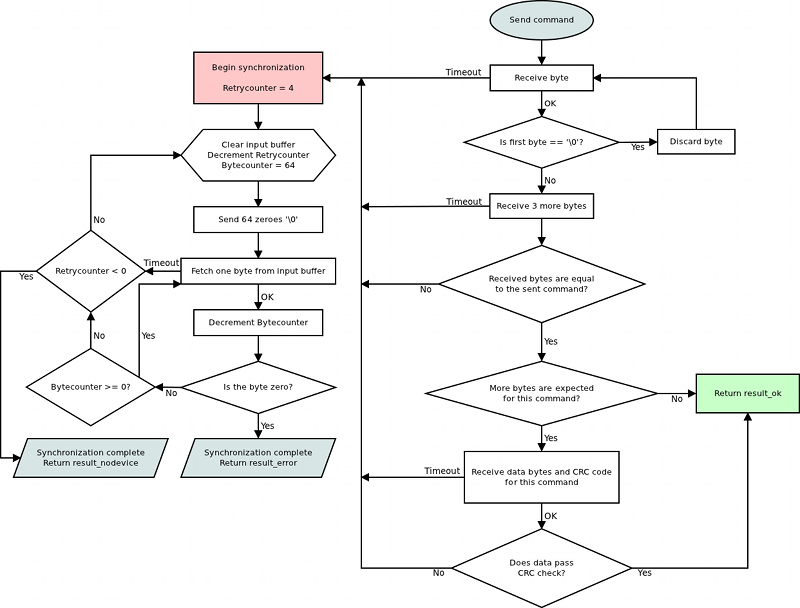
There are no command codes that start with a zero byte (‘\0’). This allows for a following synchronization procedure: controller always answers with a zero byte if the first command byte is zero, PC ignores first response byte if it is a zero byte. Then, if synchronization is disrupted on either side the following algorithm is used:
In case PC receives “errc”, “errd” or a wrong command answer code, then PC sends 4 to 250 zeroes to the controller (250 byte limit is caused by input buffer length and usage of I2C protocol, less than 4 zeroes do not guarantee successful resynchronization). During this time PC continuously reads incoming bytes from the controller until the first zero is received and stops sending and receiving right after that.
Received zero byte is likely not a part of a response to a previous command because on error PC receives “errc”/”errd” response. It is possible in rare cases, then synchronization procedure will start again. Therefore first zero byte received by the PC means that controller input buffer is already empty and will remain so until any command is sent. Right after receiving first zero byte from the controller PC is ready to transmit next command code. The rest of zero bytes in transit will be ignored because they will be received before controller response.
This completes the zero byte synchronization procedure.
6.2.4. Library-side error processing
Nearly every library function has a return status of type result_t.
After sending command to the controller library reads incoming bytes until a non-zero byte is received. All zero bytes are ignored. Library reads first 4 bytes and compares them to the command code. It then waits for data section and CRC, if needed. If first 4 received bytes do not match the sent command identifier, then zero byte synchronization procedure is launched, command is considered to be sent unsuccessfully. If first 4 received bytes match the sent command identifier and command has data section, but the received CRC doesn’t match CRC calculated from the received data, then zero byte synchronization procedure is launched, command is considered to be sent unsuccessfully. If a timeout is reached while the library is waiting for the controller response, then zero byte synchronization procedure is launched, command is considered to be sent unsuccessfully.
If no errors were detected, then command is considered to be successfully completed and result_ok is returned.
6.2.4.1. Library return codes
- result_ok. No errors detected.
- result_error. Generic error. Can happen because of hardware problems, empty port buffer, timeout or successfull synchronization after an error. Another common reason for this error is protocol version mismatch between controller firmware and PC library.
- result_nodevice. Error opening device, lost connection or failed synchronization. Device reopen and/or user action is required.
If a function returns an error values of all parameters it writes to are undefined. Error code may be accompanied by detailed error description output to system log (Unix-like OS) or standard error (Windows-like OS).
6.2.4.2. Zero byte synchronization procedure
Synchronization is performed by means of sending zero (‘\0’) bytes and reading bytes until a zero byte is received. Optionally one may clear port buffer at the end of synchronization procedure. Initially 64 zero bytes are sent. If there were no zero bytes received during the timeout, then a string of 64 bytes is sent 3 more times. After 4 unsuccessful attempts and no zero bytes received device is considered lost. In this case library should return result_nodevice error code. In case of successful syncronization library returns result_error.
6.2.5. Controller error response types
6.2.5.1. ERRC
Answer: (4 bytes)
Code: “errc” or 0x63727265
| uint32_t | errc | Command error |
Description:
Controller answers with “errc” if the command is either not recognized or cannot be processed and sets the correspoding bit in status data structure.
6.2.5.2. ERRD
Answer: (4 bytes)
Code: “errd” or 0x64727265
| uint32_t | errd | Data error |
Description:
Controller answers with “errd” if the CRC of the data section computed by the controller doesn’t match the received CRC field and sets the correspoding bit in status data structure.
6.2.5.3. ERRV
Answer: (4 bytes)
Code: “errv” or 0x76727265
| uint32_t | errv | Value error |
Description:
Controller answers with “errv” if any of the values in the command are out of acceptable range and can not be applied. Inacceptable value is replaced by a rounded, truncated or default value. Controller also sets the correspoding bit in status data structure.
6.2.6. All controller commands
6.2.6.1. Command GACC
Command code (CMD): “gacc” or 0x63636167.
Request: (4 bytes)
| uint32_t | CMD | Command |
Answer: (114 bytes)
| uint32_t | CMD | Command |
| int8_t | MagneticBrakeInfo | The manufacturer and the part number of magnetic brake, the maximum string length is 24 characters. |
| float | MBRatedVoltage | Rated voltage for controlling the magnetic brake (B). Data type: float. |
| float | MBRatedCurrent | Rated current for controlling the magnetic brake (A). Data type: float. |
| float | MBTorque | Retention moment (mN m). Data type: float. |
| uint32_t | MBSettings | Flags of magnetic brake settings |
| 0x1 - MB_AVAILABLE | If flag is set the magnetic brake is available | |
| 0x2 - MB_POWERED_HOLD | If this flag is set the magnetic brake is on when powered | |
| int8_t | TemperatureSensorInfo | The manufacturer and the part number of the temperature sensor, the maximum string length: 24 characters. |
| float | TSMin | The minimum measured temperature (degrees Celsius) Data type: float. |
| float | TSMax | The maximum measured temperature (degrees Celsius) Data type: float. |
| float | TSGrad | The temperature gradient (V/degrees Celsius). Data type: float. |
| uint32_t | TSSettings | Flags of temperature sensor settings. |
| 0x7 - TS_TYPE_BITS | Bits of the temperature sensor type | |
| 0x0 - TS_TYPE_UNKNOWN | Unknow type of sensor | |
| 0x1 - TS_TYPE_THERMOCOUPLE | Thermocouple | |
| 0x2 - TS_TYPE_SEMICONDUCTOR | The semiconductor temperature sensor | |
| 0x8 - TS_AVAILABLE | If flag is set the temperature sensor is available | |
| uint32_t | LimitSwitchesSettings | Flags of limit switches settings. |
| 0x1 - LS_ON_SW1_AVAILABLE | If flag is set the limit switch connnected to pin SW1 is available | |
| 0x2 - LS_ON_SW2_AVAILABLE | If flag is set the limit switch connnected to pin SW2 is available | |
| 0x4 - LS_SW1_ACTIVE_LOW | If flag is set the limit switch connnected to pin SW1 is triggered by a low level on pin | |
| 0x8 - LS_SW2_ACTIVE_LOW | If flag is set the limit switch connnected to pin SW2 is triggered by a low level on pin | |
| 0x10 - LS_SHORTED | If flag is set the Limit switches is shorted | |
| uint8_t | Reserved [24] | Reserved (24 bytes) |
| uint16_t | CRC | Checksum |
Description: Read additional accessories information from EEPROM.
6.2.6.2. Command GBRK
Command code (CMD): “gbrk” or 0x6B726267.
Request: (4 bytes)
| uint32_t | CMD | Command |
Answer: (25 bytes)
| uint32_t | CMD | Command |
| uint16_t | t1 | Time in ms between turn on motor power and turn off brake. |
| uint16_t | t2 | Time in ms between turn off brake and moving readiness. All moving commands will execute after this interval. |
| uint16_t | t3 | Time in ms between motor stop and turn on brake. |
| uint16_t | t4 | Time in ms between turn on brake and turn off motor power. |
| uint8_t | BrakeFlags | Flags. |
| 0x1 - BRAKE_ENABLED | Brake control is enabled, if this flag is set. | |
| 0x2 - BRAKE_ENG_PWROFF | Brake turns off power of step motor, if this flag is set. | |
| uint8_t | Reserved [10] | Reserved (10 bytes) |
| uint16_t | CRC | Checksum |
Description: Read settings of brake control.
6.2.6.3. Command GCAL
Command code (CMD): “gcal” or 0x6C616367.
Request: (4 bytes)
| uint32_t | CMD | Command |
Answer: (118 bytes)
| uint32_t | CMD | Command |
| float | CSS1_A | Scaling factor for the analogue measurements of the winding A current. |
| float | CSS1_B | Shift factor for the analogue measurements of the winding A current. |
| float | CSS2_A | Scaling factor for the analogue measurements of the winding B current. |
| float | CSS2_B | Shift factor for the analogue measurements of the winding B current. |
| float | FullCurrent_A | Scaling factor for the analogue measurements of the full current. |
| float | FullCurrent_B | Shift factor for the analogue measurements of the full current. |
| uint8_t | Reserved [88] | Reserved (88 bytes) |
| uint16_t | CRC | Checksum |
Description: Read calibration settings. This function fill structure with calibration settings.
6.2.6.4. Command GCTL
Command code (CMD): “gctl” or 0x6C746367.
Request: (4 bytes)
| uint32_t | CMD | Command |
Answer: (93 bytes)
| uint32_t | CMD | Command |
| uint32_t | MaxSpeed | Array of speeds (full step) using with joystick and button control. Range: 0..100000. |
| uint8_t | uMaxSpeed | Array of speeds (1/256 microstep) using with joystick and button control. |
| uint16_t | Timeout | timeout[i] is time in ms, after that max_speed[i+1] is applying. It is using with buttons control only. |
| uint16_t | MaxClickTime | Maximum click time. Prior to the expiration of this time the first speed isn’t enabled. |
| uint16_t | Flags | Flags. |
| 0x3 - CONTROL_MODE_BITS | Bits to control engine by joystick or buttons. | |
| 0x0 - CONTROL_MODE_OFF | Control is disabled. | |
| 0x1 - CONTROL_MODE_JOY | Control by joystick. | |
| 0x2 - CONTROL_MODE_LR | Control by left/right buttons. | |
| 0x4 - CONTROL_BTN_LEFT_PUSHED_OPEN | Pushed left button corresponds to open contact, if this flag is set. | |
| 0x8 - CONTROL_BTN_RIGHT_PUSHED_OPEN | Pushed right button corresponds to open contact, if this flag is set. | |
| int32_t | DeltaPosition | Shift (delta) of position |
| int16_t | uDeltaPosition | Fractional part of the shift in micro steps. Is only used with stepper motor. Range: -255..255. |
| uint8_t | Reserved [9] | Reserved (9 bytes) |
| uint16_t | CRC | Checksum |
Description: Read settings of motor control. When choosing CTL_MODE = 1 switches motor control with the joystick. In this mode, the joystick to the maximum engine tends Move at MaxSpeed [i], where i = 0 if the previous use This mode is not selected another i. Buttons switch the room rate i. When CTL_MODE = 2 is switched on motor control using the Left / right. When you click on the button motor starts to move in the appropriate direction at a speed MaxSpeed [0], at the end of time Timeout [i] motor move at a speed MaxSpeed [i+1]. at Transition from MaxSpeed [i] on MaxSpeed [i +1] to acceleration, as usual.
6.2.6.5. Command GCTP
Command code (CMD): “gctp” or 0x70746367.
Request: (4 bytes)
| uint32_t | CMD | Command |
Answer: (18 bytes)
| uint32_t | CMD | Command |
| uint8_t | CTPMinError | Minimum contrast steps from step motor encoder position, wich set STATE_CTP_ERROR flag. Measured in steps step motor. |
| uint8_t | CTPFlags | Flags. |
| 0x1 - CTP_ENABLED | Position control is enabled, if flag set. | |
| 0x2 - CTP_BASE | Position control is based on revolution sensor, if this flag is set; otherwise it is based on encoder. | |
| 0x4 - CTP_ALARM_ON_ERROR | Set ALARM on mismatch, if flag set. | |
| 0x8 - REV_SENS_INV | Sensor is active when it 0 and invert makes active level 1. That is, if you do not invert, it is normal logic - 0 is the activation. | |
| 0x10 - CTP_ERROR_CORRECTION | Correct errors which appear when slippage if the flag is set. It works only with the encoder. Incompatible with flag CTP_ALARM_ON_ERROR. | |
| uint8_t | Reserved [10] | Reserved (10 bytes) |
| uint16_t | CRC | Checksum |
Description: Read settings of control position(is only used with stepper motor). When controlling the step motor with encoder (CTP_BASE 0) it is possible to detect the loss of steps. The controller knows the number of steps per revolution (GENG :: StepsPerRev) and the encoder resolution (GFBS :: IPT). When the control (flag CTP_ENABLED), the controller stores the current position in the footsteps of SM and the current position of the encoder. Further, at each step of the position encoder is converted into steps and if the difference is greater CTPMinError, a flag STATE_CTP_ERROR. When controlling the step motor with speed sensor (CTP_BASE 1), the position is controlled by him. The active edge of input clock controller stores the current value of steps. Further, at each turn checks how many steps shifted. When a mismatch CTPMinError a flag STATE_CTP_ERROR.
6.2.6.6. Command GEDS
Command code (CMD): “geds” or 0x73646567.
Request: (4 bytes)
| uint32_t | CMD | Command |
Answer: (26 bytes)
| uint32_t | CMD | Command |
| uint8_t | BorderFlags | Border flags, specify types of borders and motor behaviour on borders. |
| 0x1 - BORDER_IS_ENCODER | Borders are fixed by predetermined encoder values, if set; borders position on limit switches, if not set. | |
| 0x2 - BORDER_STOP_LEFT | Motor should stop on left border. | |
| 0x4 - BORDER_STOP_RIGHT | Motor should stop on right border. | |
| 0x8 - BORDERS_SWAP_MISSET_DETECTION | Motor should stop on both borders. Need to save motor then wrong border settings is set | |
| uint8_t | EnderFlags | Ender flags, specify electrical behaviour of limit switches like order and pulled positions. |
| 0x1 - ENDER_SWAP | First limit switch on the right side, if set; otherwise on the left side. | |
| 0x2 - ENDER_SW1_ACTIVE_LOW | 1 - Limit switch connnected to pin SW1 is triggered by a low level on pin. | |
| 0x4 - ENDER_SW2_ACTIVE_LOW | 1 - Limit switch connnected to pin SW2 is triggered by a low level on pin. | |
| int32_t | LeftBorder | Left border position, used if BORDER_IS_ENCODER flag is set. |
| int16_t | uLeftBorder | Left border position in 1/256 microsteps(used with stepper motor only). Range: -255..255. |
| int32_t | RightBorder | Right border position, used if BORDER_IS_ENCODER flag is set. |
| int16_t | uRightBorder | Right border position in 1/256 microsteps. Used with stepper motor only. Range: -255..255. |
| uint8_t | Reserved [6] | Reserved (6 bytes) |
| uint16_t | CRC | Checksum |
Description: Read border and limit switches settings.
6.2.6.7. Command GEIO
Command code (CMD): “geio” or 0x6F696567.
Request: (4 bytes)
| uint32_t | CMD | Command |
Answer: (18 bytes)
| uint32_t | CMD | Command |
| uint8_t | EXTIOSetupFlags | Configuration flags of the external I-O |
| 0x1 - EXTIO_SETUP_OUTPUT | EXTIO works as output if flag is set, works as input otherwise. | |
| 0x2 - EXTIO_SETUP_INVERT | Interpret EXTIO states and fronts inverted if flag is set. Falling front as input event and low logic level as active state. | |
| uint8_t | EXTIOModeFlags | Flags mode settings external I-O |
| 0xf - EXTIO_SETUP_MODE_IN_BITS | Bits of the behaviour selector when the signal on input goes to the active state. | |
| 0x0 - EXTIO_SETUP_MODE_IN_NOP | Do nothing. | |
| 0x1 - EXTIO_SETUP_MODE_IN_STOP | Issue STOP command, ceasing the engine movement. | |
| 0x2 - EXTIO_SETUP_MODE_IN_PWOF | Issue PWOF command, powering off all engine windings. | |
| 0x3 - EXTIO_SETUP_MODE_IN_MOVR | Issue MOVR command with last used settings. | |
| 0x4 - EXTIO_SETUP_MODE_IN_HOME | Issue HOME command. | |
| 0x5 - EXTIO_SETUP_MODE_IN_ALARM | Set Alarm when the signal goes to the active state. | |
| 0xf0 - EXTIO_SETUP_MODE_OUT_BITS | Bits of the output behaviour selection. | |
| 0x0 - EXTIO_SETUP_MODE_OUT_OFF | EXTIO pin always set in inactive state. | |
| 0x10 - EXTIO_SETUP_MODE_OUT_ON | EXTIO pin always set in active state. | |
| 0x20 - EXTIO_SETUP_MODE_OUT_MOVING | EXTIO pin stays active during moving state. | |
| 0x30 - EXTIO_SETUP_MODE_OUT_ALARM | EXTIO pin stays active during Alarm state. | |
| 0x40 - EXTIO_SETUP_MODE_OUT_MOTOR_ON | EXTIO pin stays active when windings are powered. | |
| 0x50 - EXTIO_SETUP_MODE_OUT_MOTOR_FOUND | EXTIO pin stays active when motor is connected (first winding). | |
| uint8_t | Reserved [10] | Reserved (10 bytes) |
| uint16_t | CRC | Checksum |
Description: Read EXTIO settings. This function reads a structure with a set of EXTIO settings from controller’s memory.
6.2.6.8. Command GENG
Command code (CMD): “geng” or 0x676E6567.
Request: (4 bytes)
| uint32_t | CMD | Command |
Answer: (34 bytes)
| uint32_t | CMD | Command |
| uint16_t | NomVoltage | Rated voltage in tens of mV. Controller will keep the voltage drop on motor below this value if ENGINE_LIMIT_VOLT flag is set (used with DC only). |
| uint16_t | NomCurrent | Rated current. Controller will keep current consumed by motor below this value if ENGINE_LIMIT_CURR flag is set. Range: 15..8000 |
| uint32_t | NomSpeed | Nominal (maximum) speed (in whole steps/s or rpm for DC and stepper motor as a master encoder). Controller will keep motor shaft RPM below this value if ENGINE_LIMIT_RPM flag is set. Range: 1..100000. |
| uint8_t | uNomSpeed | The fractional part of a nominal speed in microsteps (is only used with stepper motor). |
| uint16_t | EngineFlags | Set of flags specify motor shaft movement algorithm and list of limitations |
| 0x1 - ENGINE_REVERSE | Reverse flag. It determines motor shaft rotation direction that corresponds to feedback counts increasing. If not set (default), motor shaft rotation direction under positive voltage corresponds to feedback counts increasing and vice versa. Change it if you see that positive directions on motor and feedback are opposite. | |
| 0x2 - ENGINE_CURRENT_AS_RMS | Engine current meaning flag. If the flag is unset, then engine current value is interpreted as maximum amplitude value. If the flag is set, then engine current value is interpreted as root mean square current value (for stepper) or as the current value calculated from the maximum heat dissipation (bldc). | |
| 0x4 - ENGINE_MAX_SPEED | Max speed flag. If it is set, engine uses maximum speed achievable with the present engine settings as nominal speed. | |
| 0x8 - ENGINE_ANTIPLAY | Play compensation flag. If it set, engine makes backlash (play) compensation procedure and reach the predetermined position accurately on low speed. | |
| 0x10 - ENGINE_ACCEL_ON | Acceleration enable flag. If it set, motion begins with acceleration and ends with deceleration. | |
| 0x20 - ENGINE_LIMIT_VOLT | Maximum motor voltage limit enable flag(is only used with DC motor). | |
| 0x40 - ENGINE_LIMIT_CURR | Maximum motor current limit enable flag(is only used with DC motor). | |
| 0x80 - ENGINE_LIMIT_RPM | Maximum motor speed limit enable flag. | |
| int16_t | Antiplay | Number of pulses or steps for backlash (play) compensation procedure. Used if ENGINE_ANTIPLAY flag is set. |
| uint8_t | MicrostepMode | Settings of microstep mode(Used with stepper motor only). |
| 0x1 - MICROSTEP_MODE_FULL | Full step mode. | |
| 0x2 - MICROSTEP_MODE_FRAC_2 | 1/2 step mode. | |
| 0x3 - MICROSTEP_MODE_FRAC_4 | 1/4 step mode. | |
| 0x4 - MICROSTEP_MODE_FRAC_8 | 1/8 step mode. | |
| 0x5 - MICROSTEP_MODE_FRAC_16 | 1/16 step mode. | |
| 0x6 - MICROSTEP_MODE_FRAC_32 | 1/32 step mode. | |
| 0x7 - MICROSTEP_MODE_FRAC_64 | 1/64 step mode. | |
| 0x8 - MICROSTEP_MODE_FRAC_128 | 1/128 step mode. | |
| 0x9 - MICROSTEP_MODE_FRAC_256 | 1/256 step mode. | |
| uint16_t | StepsPerRev | Number of full steps per revolution(Used with stepper motor only). Range: 1..65535. |
| uint8_t | Reserved [12] | Reserved (12 bytes) |
| uint16_t | CRC | Checksum |
Description: Read engine settings. This function fill structure with set of useful motor settings stored in controller’s memory. These settings specify motor shaft movement algorithm, list of limitations and rated characteristics.
6.2.6.9. Command GENI
Command code (CMD): “geni” or 0x696E6567.
Request: (4 bytes)
| uint32_t | CMD | Command |
Answer: (70 bytes)
| uint32_t | CMD | Command |
| int8_t | Manufacturer | Manufacturer. Max string length: 16 chars. |
| int8_t | PartNumber | Series and PartNumber. Max string length: 24 chars. |
| uint8_t | Reserved [24] | Reserved (24 bytes) |
| uint16_t | CRC | Checksum |
Description: Read encoder information from EEPROM.
6.2.6.10. Command GENS
Command code (CMD): “gens” or 0x736E6567.
Request: (4 bytes)
| uint32_t | CMD | Command |
Answer: (54 bytes)
| uint32_t | CMD | Command |
| float | MaxOperatingFrequency | Max operation frequency (kHz). Data type: float. |
| float | SupplyVoltageMin | Minimum supply voltage (V). Data type: float. |
| float | SupplyVoltageMax | Maximum supply voltage (V). Data type: float. |
| float | MaxCurrentConsumption | Max current consumption (mA). Data type: float. |
| uint32_t | PPR | The number of counts per revolution |
| uint32_t | EncoderSettings | Encoder settings flags |
| 0x1 - ENCSET_DIFFERENTIAL_OUTPUT | If flag is set the encoder has differential output, else single ended output | |
| 0x4 - ENCSET_PUSHPULL_OUTPUT | If flag is set the encoder has push-pull output, else open drain output | |
| 0x10 - ENCSET_INDEXCHANNEL_PRESENT | If flag is set the encoder has index channel, else encoder hasn’t it | |
| 0x40 - ENCSET_REVOLUTIONSENSOR_PRESENT | If flag is set the encoder has revolution sensor, else encoder hasn’t it | |
| 0x100 - ENCSET_REVOLUTIONSENSOR_ACTIVE_HIGH | If flag is set the revolution sensor active state is high logic state, else active state is low logic state | |
| uint8_t | Reserved [24] | Reserved (24 bytes) |
| uint16_t | CRC | Checksum |
Description: Read encoder settings from EEPROM.
6.2.6.11. Command GENT
Command code (CMD): “gent” or 0x746E6567.
Request: (4 bytes)
| uint32_t | CMD | Command |
Answer: (14 bytes)
| uint32_t | CMD | Command |
| uint8_t | EngineType | Engine type |
| 0x0 - ENGINE_TYPE_NONE | A value that shouldn’t be used. | |
| 0x1 - ENGINE_TYPE_DC | DC motor. | |
| 0x2 - ENGINE_TYPE_2DC | 2 DC motors. | |
| 0x3 - ENGINE_TYPE_STEP | Step motor. | |
| 0x4 - ENGINE_TYPE_TEST | Duty cycle are fixed. Used only manufacturer. | |
| 0x5 - ENGINE_TYPE_BRUSHLESS | Brushless motor. | |
| uint8_t | DriverType | Driver type |
| 0x1 - DRIVER_TYPE_DISCRETE_FET | Driver with discrete FET keys. Default option. | |
| 0x2 - DRIVER_TYPE_INTEGRATE | Driver with integrated IC. | |
| 0x3 - DRIVER_TYPE_EXTERNAL | External driver. | |
| uint8_t | Reserved [6] | Reserved (6 bytes) |
| uint16_t | CRC | Checksum |
Description: Return engine type and driver type.
6.2.6.12. Command GFBS
Command code (CMD): “gfbs” or 0x73626667.
Request: (4 bytes)
| uint32_t | CMD | Command |
Answer: (18 bytes)
| uint32_t | CMD | Command |
| uint16_t | IPS | The number of encoder counts per shaft revolution. Range: 1..655535. The field is obsolete, it is recommended to write 0 to IPS and use the extended CountsPerTurn field. You may need to update the controller firmware to the latest version. |
| uint8_t | FeedbackType | Type of feedback |
| 0x1 - FEEDBACK_ENCODER | Feedback by encoder. | |
| 0x4 - FEEDBACK_EMF | Feedback by EMF. | |
| 0x5 - FEEDBACK_NONE | Feedback is absent. | |
| uint8_t | FeedbackFlags | Flags |
| 0x1 - FEEDBACK_ENC_REVERSE | Reverse count of encoder. | |
| 0xc0 - FEEDBACK_ENC_TYPE_BITS | Bits of the encoder type. | |
| 0x0 - FEEDBACK_ENC_TYPE_AUTO | Auto detect encoder type. | |
| 0x40 - FEEDBACK_ENC_TYPE_SINGLE_ENDED | Single ended encoder. | |
| 0x80 - FEEDBACK_ENC_TYPE_DIFFERENTIAL | Differential encoder. | |
| uint32_t | CountsPerTurn | The number of encoder counts per shaft revolution. Range: 1..4294967295. To use the CountsPerTurn field, write 0 in the IPS field, otherwise the value from the IPS field will be used. |
| uint8_t | Reserved [4] | Reserved (4 bytes) |
| uint16_t | CRC | Checksum |
Description: Feedback settings.
6.2.6.13. Command GGRI
Command code (CMD): “ggri” or 0x69726767.
Request: (4 bytes)
| uint32_t | CMD | Command |
Answer: (70 bytes)
| uint32_t | CMD | Command |
| int8_t | Manufacturer | Manufacturer. Max string length: 16 chars. |
| int8_t | PartNumber | Series and PartNumber. Max string length: 24 chars. |
| uint8_t | Reserved [24] | Reserved (24 bytes) |
| uint16_t | CRC | Checksum |
Description: Read gear information from EEPROM.
6.2.6.14. Command GGRS
Command code (CMD): “ggrs” or 0x73726767.
Request: (4 bytes)
| uint32_t | CMD | Command |
Answer: (58 bytes)
| uint32_t | CMD | Command |
| float | ReductionIn | Input reduction coefficient. (Output = (ReductionOut / ReductionIn) Input) Data type: float. |
| float | ReductionOut | Output reduction coefficient. (Output = (ReductionOut / ReductionIn) Input) Data type: float. |
| float | RatedInputTorque | Max continuous torque (N m). Data type: float. |
| float | RatedInputSpeed | Max speed on the input shaft (rpm). Data type: float. |
| float | MaxOutputBacklash | Output backlash of the reduction gear(degree). Data type: float. |
| float | InputInertia | Equivalent input gear inertia (g cm2). Data type: float. |
| float | Efficiency | Reduction gear efficiency (%). Data type: float. |
| uint8_t | Reserved [24] | Reserved (24 bytes) |
| uint16_t | CRC | Checksum |
Description: Read gear settings from EEPROM.
6.2.6.15. Command GHOM
Command code (CMD): “ghom” or 0x6D6F6867.
Request: (4 bytes)
| uint32_t | CMD | Command |
Answer: (33 bytes)
| uint32_t | CMD | Command |
| uint32_t | FastHome | Speed used for first motion. Range: 0..100000. |
| uint8_t | uFastHome | Part of the speed for first motion, microsteps. |
| uint32_t | SlowHome | Speed used for second motion. Range: 0..100000. |
| uint8_t | uSlowHome | Part of the speed for second motion, microsteps. |
| int32_t | HomeDelta | Distance from break point. |
| int16_t | uHomeDelta | Part of the delta distance, microsteps. Range: -255..255. |
| uint16_t | HomeFlags | Set of flags specify direction and stopping conditions. |
| 0x1 - HOME_DIR_FIRST | Flag defines direction of 1st motion after execution of home command. Direction is right, if set; otherwise left. | |
| 0x2 - HOME_DIR_SECOND | Flag defines direction of 2nd motion. Direction is right, if set; otherwise left. | |
| 0x4 - HOME_MV_SEC_EN | Use the second phase of calibration to the home position, if set; otherwise the second phase is skipped. | |
| 0x8 - HOME_HALF_MV | If the flag is set, the stop signals are ignored in start of second movement the first half-turn. | |
| 0x30 - HOME_STOP_FIRST_BITS | Bits of the first stop selector. | |
| 0x10 - HOME_STOP_FIRST_REV | First motion stops by revolution sensor. | |
| 0x20 - HOME_STOP_FIRST_SYN | First motion stops by synchronization input. | |
| 0x30 - HOME_STOP_FIRST_LIM | First motion stops by limit switch. | |
| 0xc0 - HOME_STOP_SECOND_BITS | Bits of the second stop selector. | |
| 0x40 - HOME_STOP_SECOND_REV | Second motion stops by revolution sensor. | |
| 0x80 - HOME_STOP_SECOND_SYN | Second motion stops by synchronization input. | |
| 0xc0 - HOME_STOP_SECOND_LIM | Second motion stops by limit switch. | |
| 0x100 - HOME_USE_FAST | Use the fast algorithm of calibration to the home position, if set; otherwise the traditional algorithm. | |
| uint8_t | Reserved [9] | Reserved (9 bytes) |
| uint16_t | CRC | Checksum |
Description: Read home settings. This function fill structure with settings of calibrating position.
6.2.6.16. Command GHSI
Command code (CMD): “ghsi” or 0x69736867.
Request: (4 bytes)
| uint32_t | CMD | Command |
Answer: (70 bytes)
| uint32_t | CMD | Command |
| int8_t | Manufacturer | Manufacturer. Max string length: 16 chars. |
| int8_t | PartNumber | Series and PartNumber. Max string length: 24 chars. |
| uint8_t | Reserved [24] | Reserved (24 bytes) |
| uint16_t | CRC | Checksum |
Description: Read hall sensor information from EEPROM.
6.2.6.17. Command GHSS
Command code (CMD): “ghss” or 0x73736867.
Request: (4 bytes)
| uint32_t | CMD | Command |
Answer: (50 bytes)
| uint32_t | CMD | Command |
| float | MaxOperatingFrequency | Max operation frequency (kHz). Data type: float. |
| float | SupplyVoltageMin | Minimum supply voltage (V). Data type: float. |
| float | SupplyVoltageMax | Maximum supply voltage (V). Data type: float. |
| float | MaxCurrentConsumption | Max current consumption (mA). Data type: float. |
| uint32_t | PPR | The number of counts per revolution |
| uint8_t | Reserved [24] | Reserved (24 bytes) |
| uint16_t | CRC | Checksum |
Description: Read hall sensor settings from EEPROM.
6.2.6.18. Command GJOY
Command code (CMD): “gjoy” or 0x796F6A67.
Request: (4 bytes)
| uint32_t | CMD | Command |
Answer: (22 bytes)
| uint32_t | CMD | Command |
| uint16_t | JoyLowEnd | Joystick lower end position. Range: 0..10000. |
| uint16_t | JoyCenter | Joystick center position. Range: 0..10000. |
| uint16_t | JoyHighEnd | Joystick higher end position. Range: 0..10000. |
| uint8_t | ExpFactor | Exponential nonlinearity factor. |
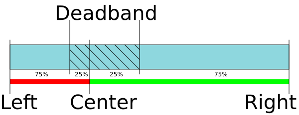
| uint8_t | DeadZone | Joystick dead zone. |
| uint8_t | JoyFlags | Joystick control flags. |
| 0x1 - JOY_REVERSE | Joystick action is reversed. Joystick deviation to the upper values correspond to negative speeds and vice versa. | |
| uint8_t | Reserved [7] | Reserved (7 bytes) |
| uint16_t | CRC | Checksum |
Description: Read settings of joystick. If joystick position is outside DeadZone limits from the central position a movement with speed, defined by the joystick DeadZone edge to 100% deviation, begins. Joystick positions inside DeadZone limits correspond to zero speed (soft stop of motion) and positions beyond Low and High limits correspond MaxSpeed [i] or -MaxSpeed [i] (see command SCTL), where i = 0 by default and can be changed with left/right buttons (see command SCTL). If next speed in list is zero (both integer and microstep parts), the button press is ignored. First speed in list shouldn’t be zero. The DeadZone ranges are illustrated on the following picture:
The relationship between the deviation and the rate is exponential, allowing no switching speed combine high mobility and accuracy. The following picture illustrates this:
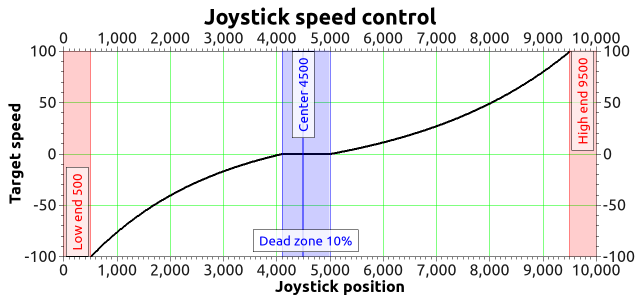
The nonlinearity parameter is adjustable. Setting it to zero makes deviation/speed relation linear.
6.2.6.19. Command GMOV
Command code (CMD): “gmov” or 0x766F6D67.
Request: (4 bytes)
| uint32_t | CMD | Command |
Answer: (30 bytes)
| uint32_t | CMD | Command |
| uint32_t | Speed | Target speed (for stepper motor: steps/s, for DC: rpm). Range: 0..100000. |
| uint8_t | uSpeed | Target speed in microstep fractions/s. Using with stepper motor only. |
| uint16_t | Accel | Motor shaft acceleration, steps/s^2(stepper motor) or RPM/s(DC). Range: 1..65535. |
| uint16_t | Decel | Motor shaft deceleration, steps/s^2(stepper motor) or RPM/s(DC). Range: 1..65535. |
| uint32_t | AntiplaySpeed | Speed in antiplay mode, full steps/s(stepper motor) or RPM(DC). Range: 0..100000. |
| uint8_t | uAntiplaySpeed | Speed in antiplay mode, 1/256 microsteps/s. Used with stepper motor only. |
| uint8_t | Reserved [10] | Reserved (10 bytes) |
| uint16_t | CRC | Checksum |
Description: Read command setup movement (speed, acceleration, threshold and etc).
6.2.6.20. Command GMTI
Command code (CMD): “gmti” or 0x69746D67.
Request: (4 bytes)
| uint32_t | CMD | Command |
Answer: (70 bytes)
| uint32_t | CMD | Command |
| int8_t | Manufacturer | Manufacturer. Max string length: 16 chars. |
| int8_t | PartNumber | Series and PartNumber. Max string length: 24 chars. |
| uint8_t | Reserved [24] | Reserved (24 bytes) |
| uint16_t | CRC | Checksum |
Description: Read motor information from EEPROM.
6.2.6.21. Command GMTS
Command code (CMD): “gmts” or 0x73746D67.
Request: (4 bytes)
| uint32_t | CMD | Command |
Answer: (112 bytes)
| uint32_t | CMD | Command |
| uint8_t | MotorType | Motor type |
| 0x0 - MOTOR_TYPE_UNKNOWN | Unknown type of engine | |
| 0x1 - MOTOR_TYPE_STEP | Step engine | |
| 0x2 - MOTOR_TYPE_DC | DC engine | |
| 0x3 - MOTOR_TYPE_BLDC | BLDC engine | |
| uint8_t | ReservedField | Reserved |
| uint16_t | Poles | Number of pole pairs for DC or BLDC motors or number of steps per rotation for stepper motor. |
| uint16_t | Phases | Number of phases for BLDC motors. |
| float | NominalVoltage | Nominal voltage on winding (B). Data type: float |
| float | NominalCurrent | Maximum direct current in winding for DC and BLDC engines, nominal current in windings for stepper motor (A). Data type: float. |
| float | NominalSpeed | Not used. Nominal speed(rpm). Used for DC and BLDC engine. Data type: float. |
| float | NominalTorque | Nominal torque(mN m). Used for DC and BLDC engine. Data type: float. |
| float | NominalPower | Nominal power(W). Used for DC and BLDC engine. Data type: float. |
| float | WindingResistance | Resistance of windings for DC engine, each of two windings for stepper motor or each of there windings for BLDC engine(Ohm). Data type: float. |
| float | WindingInductance | Inductance of windings for DC engine, each of two windings for stepper motor or each of there windings for BLDC engine(mH). Data type: float. |
| float | RotorInertia | Rotor inertia(g cm2). Data type: float. |
| float | StallTorque | Torque hold position for a stepper motor or torque at a motionless rotor for other types of engines (mN m). Data type: float. |
| float | DetentTorque | Holding torque position with un-powered coils (mN m). Data type: float. |
| float | TorqueConstant | Torque constant, which determines the aspect ratio of maximum moment of force from the rotor current flowing in the coil (mN m / A). Used mainly for DC motors. Data type: float. |
| float | SpeedConstant | Velocity constant, which determines the value or amplitude of the induced voltage on the motion of DC or BLDC motor (rpm / V) or stepper motor (steps/s / V). Data type: float. |
| float | SpeedTorqueGradient | Speed torque gradient (rpm / mN m). Data type: float. |
| float | MechanicalTimeConstant | Mechanical time constant (ms). Data type: float. |
| float | MaxSpeed | The maximum speed for stepper motors (steps/s) or DC and BLDC motors (rmp). Data type: float. |
| float | MaxCurrent | The maximum current in the winding (A). Data type: float. |
| float | MaxCurrentTime | Safe duration of overcurrent in the winding (ms). Data type: float. |
| float | NoLoadCurrent | The current consumption in idle mode (A). Used for DC and BLDC motors. Data type: float. |
| float | NoLoadSpeed | Idle speed (rpm). Used for DC and BLDC motors. Data type: float. |
| uint8_t | Reserved [24] | Reserved (24 bytes) |
| uint16_t | CRC | Checksum |
Description: Read motor settings from EEPROM.
6.2.6.22. Command GNME
Command code (CMD): “gnme” or 0x656D6E67.
Request: (4 bytes)
| uint32_t | CMD | Command |
Answer: (30 bytes)
| uint32_t | CMD | Command |
| int8_t | PositionerName | User positioner name. Can be set by user for his/her convinience. Max string length: 16 chars. |
| uint8_t | Reserved [8] | Reserved (8 bytes) |
| uint16_t | CRC | Checksum |
Description: Read user stage name from EEPROM.
6.2.6.23. Command GNMF
Command code (CMD): “gnmf” or 0x666D6E67.
Request: (4 bytes)
| uint32_t | CMD | Command |
Answer: (30 bytes)
| uint32_t | CMD | Command |
| int8_t | ControllerName | User conroller name. Can be set by user for his/her convinience. Max string length: 16 chars. |
| uint8_t | CtrlFlags | Internal controller settings. |
| 0x1 - EEPROM_PRECEDENCE | If the flag is set settings from external EEPROM override controller settings. | |
| uint8_t | Reserved [7] | Reserved (7 bytes) |
| uint16_t | CRC | Checksum |
Description: Read user controller name and flags of setting from FRAM.
6.2.6.24. Command GNVM
Command code (CMD): “gnvm” or 0x6D766E67.
Request: (4 bytes)
| uint32_t | CMD | Command |
Answer: (36 bytes)
| uint32_t | CMD | Command |
| uint32_t | UserData | User data. Can be set by user for his/her convinience. Each element of the array stores only 32 bits of user data. This is important on systems where an int type contains more than 4 bytes. For example that all amd64 systems. |
| uint8_t | Reserved [2] | Reserved (2 bytes) |
| uint16_t | CRC | Checksum |
Description: Read userdata from FRAM.
6.2.6.25. Command GPID
Command code (CMD): “gpid” or 0x64697067.
Request: (4 bytes)
| uint32_t | CMD | Command |
Answer: (48 bytes)
| uint32_t | CMD | Command |
| uint16_t | KpU | Proportional gain for voltage PID routine |
| uint16_t | KiU | Integral gain for voltage PID routine |
| uint16_t | KdU | Differential gain for voltage PID routine |
| float | Kpf | Proportional gain for BLDC position PID routine |
| float | Kif | Integral gain for BLDC position PID routine |
| float | Kdf | Differential gain for BLDC position PID routine |
| uint8_t | Reserved [24] | Reserved (24 bytes) |
| uint16_t | CRC | Checksum |
Description: Read PID settings. This function fill structure with set of motor PID settings stored in controller’s memory. These settings specify behaviour of PID routine for positioner. These factors are slightly different for different positioners. All boards are supplied with standard set of PID setting on controller’s flash memory.
6.2.6.26. Command GPWR
Command code (CMD): “gpwr” or 0x72777067.
Request: (4 bytes)
| uint32_t | CMD | Command |
Answer: (20 bytes)
| uint32_t | CMD | Command |
| uint8_t | HoldCurrent | Current in holding regime, percent of nominal. Range: 0..100. |
| uint16_t | CurrReductDelay | Time in ms from going to STOP state to reducting current. |
| uint16_t | PowerOffDelay | Time in s from going to STOP state to turning power off. |
| uint16_t | CurrentSetTime | Time in ms to reach nominal current. |
| uint8_t | PowerFlags | Flags with parameters of power control. |
| 0x1 - POWER_REDUCT_ENABLED | Current reduction enabled after CurrReductDelay, if this flag is set. | |
| 0x2 - POWER_OFF_ENABLED | Power off enabled after PowerOffDelay, if this flag is set. | |
| 0x4 - POWER_SMOOTH_CURRENT | Current ramp-up/down is performed smoothly during current_set_time, if this flag is set. | |
| uint8_t | Reserved [6] | Reserved (6 bytes) |
| uint16_t | CRC | Checksum |
Description: Read settings of step motor power control. Used with stepper motor only.
6.2.6.27. Command GSEC
Command code (CMD): “gsec” or 0x63657367.
Request: (4 bytes)
| uint32_t | CMD | Command |
Answer: (28 bytes)
| uint32_t | CMD | Command |
| uint16_t | LowUpwrOff | Lower voltage limit to turn off the motor, tens of mV. |
| uint16_t | CriticalIpwr | Maximum motor current which triggers ALARM state, in mA. |
| uint16_t | CriticalUpwr | Maximum motor voltage which triggers ALARM state, tens of mV. |
| uint16_t | CriticalT | Maximum temperature, which triggers ALARM state, in tenths of degrees Celcius. |
| uint16_t | CriticalIusb | Maximum USB current which triggers ALARM state, in mA. |
| uint16_t | CriticalUusb | Maximum USB voltage which triggers ALARM state, tens of mV. |
| uint16_t | MinimumUusb | Minimum USB voltage which triggers ALARM state, tens of mV. |
| uint8_t | Flags | Critical parameter flags. |
| 0x1 - ALARM_ON_DRIVER_OVERHEATING | If this flag is set enter Alarm state on driver overheat signal. | |
| 0x2 - LOW_UPWR_PROTECTION | If this flag is set turn off motor when voltage is lower than LowUpwrOff. | |
| 0x4 - H_BRIDGE_ALERT | If this flag is set then turn off the power unit with a signal problem in one of the transistor bridge. | |
| 0x8 - ALARM_ON_BORDERS_SWAP_MISSET | If this flag is set enter Alarm state on borders swap misset | |
| 0x10 - ALARM_FLAGS_STICKING | If this flag is set only a STOP command can turn all alarms to 0 | |
| 0x20 - USB_BREAK_RECONNECT | If this flag is set USB brake reconnect module will be enable | |
| uint8_t | Reserved [7] | Reserved (7 bytes) |
| uint16_t | CRC | Checksum |
Description: Read protection settings.
6.2.6.28. Command GSNI
Command code (CMD): “gsni” or 0x696E7367.
Request: (4 bytes)
| uint32_t | CMD | Command |
Answer: (28 bytes)
| uint32_t | CMD | Command |
| uint8_t | SyncInFlags | Input synchronization flags |
| 0x1 - SYNCIN_ENABLED | Synchronization in mode is enabled, if this flag is set. | |
| 0x2 - SYNCIN_INVERT | Trigger on falling edge if flag is set, on rising edge otherwise. | |
| 0x4 - SYNCIN_GOTOPOSITION | The engine is go to position specified in Position and uPosition, if this flag is set. And it is shift on the Position and uPosition, if this flag is unset | |
| uint16_t | ClutterTime | Input synchronization pulse dead time (mks). |
| int32_t | Position | Desired position or shift (whole steps) |
| int16_t | uPosition | The fractional part of a position or shift in microsteps. Is used with stepper motor. Range: -255..255. |
| uint32_t | Speed | Target speed (for stepper motor: steps/s, for DC: rpm). Range: 0..100000. |
| uint8_t | uSpeed | Target speed in microsteps/s. Using with stepper motor only. |
| uint8_t | Reserved [8] | Reserved (8 bytes) |
| uint16_t | CRC | Checksum |
Description: Read input synchronization settings. This function fill structure with set of input synchronization settings, modes, periods and flags, that specify behaviour of input synchronization. All boards are supplied with standard set of these settings.
6.2.6.29. Command GSNO
Command code (CMD): “gsno” or 0x6F6E7367.
Request: (4 bytes)
| uint32_t | CMD | Command |
Answer: (16 bytes)
| uint32_t | CMD | Command |
| uint8_t | SyncOutFlags | Output synchronization flags |
| 0x1 - SYNCOUT_ENABLED | Synchronization out pin follows the synchronization logic, if set. It governed by SYNCOUT_STATE flag otherwise. | |
| 0x2 - SYNCOUT_STATE | When output state is fixed by negative SYNCOUT_ENABLED flag, the pin state is in accordance with this flag state. | |
| 0x4 - SYNCOUT_INVERT | Low level is active, if set, and high level is active otherwise. | |
| 0x8 - SYNCOUT_IN_STEPS | Use motor steps/encoder pulses instead of milliseconds for output pulse generation if the flag is set. | |
| 0x10 - SYNCOUT_ONSTART | Generate synchronization pulse when movement starts. | |
| 0x20 - SYNCOUT_ONSTOP | Generate synchronization pulse when movement stops. | |
| 0x40 - SYNCOUT_ONPERIOD | Generate synchronization pulse every SyncOutPeriod encoder pulses. | |
| uint16_t | SyncOutPulseSteps | This value specifies duration of output pulse. It is measured microseconds when SYNCOUT_IN_STEPS flag is cleared or in encoder pulses or motor steps when SYNCOUT_IN_STEPS is set. |
| uint16_t | SyncOutPeriod | This value specifies number of encoder pulses or steps between two output synchronization pulses when SYNCOUT_ONPERIOD is set. |
| uint32_t | Accuracy | This is the neighborhood around the target coordinates, which is getting hit in the target position and the momentum generated by the stop. |
| uint8_t | uAccuracy | This is the neighborhood around the target coordinates in micro steps (only used with stepper motor). |
| uint16_t | CRC | Checksum |
Description: Read output synchronization settings. This function fill structure with set of output synchronization settings, modes, periods and flags, that specify behaviour of output synchronization. All boards are supplied with standard set of these settings.
6.2.6.30. Command GSTI
Command code (CMD): “gsti” or 0x69747367.
Request: (4 bytes)
| uint32_t | CMD | Command |
Answer: (70 bytes)
| uint32_t | CMD | Command |
| int8_t | Manufacturer | Manufacturer. Max string length: 16 chars. |
| int8_t | PartNumber | Series and PartNumber. Max string length: 24 chars. |
| uint8_t | Reserved [24] | Reserved (24 bytes) |
| uint16_t | CRC | Checksum |
Description: Read stage information from EEPROM.
6.2.6.31. Command GSTS
Command code (CMD): “gsts” or 0x73747367.
Request: (4 bytes)
| uint32_t | CMD | Command |
Answer: (70 bytes)
| uint32_t | CMD | Command |
| float | LeadScrewPitch | Lead screw pitch (mm). Data type: float. |
| int8_t | Units | Units for MaxSpeed and TravelRange fields of the structure (steps, degrees, mm, …). Max string length: 8 chars. |
| float | MaxSpeed | Max speed (Units/c). Data type: float. |
| float | TravelRange | Travel range (Units). Data type: float. |
| float | SupplyVoltageMin | Supply voltage minimum (V). Data type: float. |
| float | SupplyVoltageMax | Supply voltage maximum (V). Data type: float. |
| float | MaxCurrentConsumption | Max current consumption (A). Data type: float. |
| float | HorizontalLoadCapacity | Horizontal load capacity (kg). Data type: float. |
| float | VerticalLoadCapacity | Vertical load capacity (kg). Data type: float. |
| uint8_t | Reserved [24] | Reserved (24 bytes) |
| uint16_t | CRC | Checksum |
Description: Read stage settings from EEPROM.
6.2.6.32. Command GURT
Command code (CMD): “gurt” or 0x74727567.
Request: (4 bytes)
| uint32_t | CMD | Command |
Answer: (16 bytes)
| uint32_t | CMD | Command |
| uint32_t | Speed | UART speed |
| uint16_t | UARTSetupFlags | UART setup flags |
| 0x3 - UART_PARITY_BITS | Bits of the parity. | |
| 0x0 - UART_PARITY_BIT_EVEN | Parity bit 1, if even | |
| 0x1 - UART_PARITY_BIT_ODD | Parity bit 1, if odd | |
| 0x2 - UART_PARITY_BIT_SPACE | Parity bit always 0 | |
| 0x3 - UART_PARITY_BIT_MARK | Parity bit always 1 | |
| 0x4 - UART_PARITY_BIT_USE | None parity | |
| 0x8 - UART_STOP_BIT | If set - one stop bit, else two stop bit | |
| uint8_t | Reserved [4] | Reserved (4 bytes) |
| uint16_t | CRC | Checksum |
Description: Read UART settings. This function fill structure with UART settings.
6.2.6.33. Command SACC
Command code (CMD): “sacc” or 0x63636173.
Request: (114 bytes)
| uint32_t | CMD | Command |
| int8_t | MagneticBrakeInfo | The manufacturer and the part number of magnetic brake, the maximum string length is 24 characters. |
| float | MBRatedVoltage | Rated voltage for controlling the magnetic brake (B). Data type: float. |
| float | MBRatedCurrent | Rated current for controlling the magnetic brake (A). Data type: float. |
| float | MBTorque | Retention moment (mN m). Data type: float. |
| uint32_t | MBSettings | Flags of magnetic brake settings |
| 0x1 - MB_AVAILABLE | If flag is set the magnetic brake is available | |
| 0x2 - MB_POWERED_HOLD | If this flag is set the magnetic brake is on when powered | |
| int8_t | TemperatureSensorInfo | The manufacturer and the part number of the temperature sensor, the maximum string length: 24 characters. |
| float | TSMin | The minimum measured temperature (degrees Celsius) Data type: float. |
| float | TSMax | The maximum measured temperature (degrees Celsius) Data type: float. |
| float | TSGrad | The temperature gradient (V/degrees Celsius). Data type: float. |
| uint32_t | TSSettings | Flags of temperature sensor settings. |
| 0x7 - TS_TYPE_BITS | Bits of the temperature sensor type | |
| 0x0 - TS_TYPE_UNKNOWN | Unknow type of sensor | |
| 0x1 - TS_TYPE_THERMOCOUPLE | Thermocouple | |
| 0x2 - TS_TYPE_SEMICONDUCTOR | The semiconductor temperature sensor | |
| 0x8 - TS_AVAILABLE | If flag is set the temperature sensor is available | |
| uint32_t | LimitSwitchesSettings | Flags of limit switches settings. |
| 0x1 - LS_ON_SW1_AVAILABLE | If flag is set the limit switch connnected to pin SW1 is available | |
| 0x2 - LS_ON_SW2_AVAILABLE | If flag is set the limit switch connnected to pin SW2 is available | |
| 0x4 - LS_SW1_ACTIVE_LOW | If flag is set the limit switch connnected to pin SW1 is triggered by a low level on pin | |
| 0x8 - LS_SW2_ACTIVE_LOW | If flag is set the limit switch connnected to pin SW2 is triggered by a low level on pin | |
| 0x10 - LS_SHORTED | If flag is set the Limit switches is shorted | |
| uint8_t | Reserved [24] | Reserved (24 bytes) |
| uint16_t | CRC | Checksum |
Answer: (4 bytes)
| uint32_t | CMD | Command |
Description: Set additional accessories information to EEPROM. Can be used by manufacturer only.
6.2.6.34. Command SBRK
Command code (CMD): “sbrk” or 0x6B726273.
Request: (25 bytes)
| uint32_t | CMD | Command |
| uint16_t | t1 | Time in ms between turn on motor power and turn off brake. |
| uint16_t | t2 | Time in ms between turn off brake and moving readiness. All moving commands will execute after this interval. |
| uint16_t | t3 | Time in ms between motor stop and turn on brake. |
| uint16_t | t4 | Time in ms between turn on brake and turn off motor power. |
| uint8_t | BrakeFlags | Flags. |
| 0x1 - BRAKE_ENABLED | Brake control is enabled, if this flag is set. | |
| 0x2 - BRAKE_ENG_PWROFF | Brake turns off power of step motor, if this flag is set. | |
| uint8_t | Reserved [10] | Reserved (10 bytes) |
| uint16_t | CRC | Checksum |
Answer: (4 bytes)
| uint32_t | CMD | Command |
Description: Set settings of brake control.
6.2.6.35. Command SCAL
Command code (CMD): “scal” or 0x6C616373.
Request: (118 bytes)
| uint32_t | CMD | Command |
| float | CSS1_A | Scaling factor for the analogue measurements of the winding A current. |
| float | CSS1_B | Shift factor for the analogue measurements of the winding A current. |
| float | CSS2_A | Scaling factor for the analogue measurements of the winding B current. |
| float | CSS2_B | Shift factor for the analogue measurements of the winding B current. |
| float | FullCurrent_A | Scaling factor for the analogue measurements of the full current. |
| float | FullCurrent_B | Shift factor for the analogue measurements of the full current. |
| uint8_t | Reserved [88] | Reserved (88 bytes) |
| uint16_t | CRC | Checksum |
Answer: (4 bytes)
| uint32_t | CMD | Command |
Description: Set calibration settings. This function send structure with calibration settings to controller’s memory.
6.2.6.36. Command SCTL
Command code (CMD): “sctl” or 0x6C746373.
Request: (93 bytes)
| uint32_t | CMD | Command |
| uint32_t | MaxSpeed | Array of speeds (full step) using with joystick and button control. Range: 0..100000. |
| uint8_t | uMaxSpeed | Array of speeds (1/256 microstep) using with joystick and button control. |
| uint16_t | Timeout | timeout[i] is time in ms, after that max_speed[i+1] is applying. It is using with buttons control only. |
| uint16_t | MaxClickTime | Maximum click time. Prior to the expiration of this time the first speed isn’t enabled. |
| uint16_t | Flags | Flags. |
| 0x3 - CONTROL_MODE_BITS | Bits to control engine by joystick or buttons. | |
| 0x0 - CONTROL_MODE_OFF | Control is disabled. | |
| 0x1 - CONTROL_MODE_JOY | Control by joystick. | |
| 0x2 - CONTROL_MODE_LR | Control by left/right buttons. | |
| 0x4 - CONTROL_BTN_LEFT_PUSHED_OPEN | Pushed left button corresponds to open contact, if this flag is set. | |
| 0x8 - CONTROL_BTN_RIGHT_PUSHED_OPEN | Pushed right button corresponds to open contact, if this flag is set. | |
| int32_t | DeltaPosition | Shift (delta) of position |
| int16_t | uDeltaPosition | Fractional part of the shift in micro steps. Is only used with stepper motor. Range: -255..255. |
| uint8_t | Reserved [9] | Reserved (9 bytes) |
| uint16_t | CRC | Checksum |
Answer: (4 bytes)
| uint32_t | CMD | Command |
Description: Set settings of motor control. When choosing CTL_MODE = 1 switches motor control with the joystick. In this mode, the joystick to the maximum engine tends Move at MaxSpeed [i], where i = 0 if the previous use This mode is not selected another i. Buttons switch the room rate i. When CTL_MODE = 2 is switched on motor control using the Left / right. When you click on the button motor starts to move in the appropriate direction at a speed MaxSpeed [0], at the end of time Timeout [i] motor move at a speed MaxSpeed [i+1]. at Transition from MaxSpeed [i] on MaxSpeed [i +1] to acceleration, as usual.
6.2.6.37. Command SCTP
Command code (CMD): “sctp” or 0x70746373.
Request: (18 bytes)
| uint32_t | CMD | Command |
| uint8_t | CTPMinError | Minimum contrast steps from step motor encoder position, wich set STATE_CTP_ERROR flag. Measured in steps step motor. |
| uint8_t | CTPFlags | Flags. |
| 0x1 - CTP_ENABLED | Position control is enabled, if flag set. | |
| 0x2 - CTP_BASE | Position control is based on revolution sensor, if this flag is set; otherwise it is based on encoder. | |
| 0x4 - CTP_ALARM_ON_ERROR | Set ALARM on mismatch, if flag set. | |
| 0x8 - REV_SENS_INV | Sensor is active when it 0 and invert makes active level 1. That is, if you do not invert, it is normal logic - 0 is the activation. | |
| 0x10 - CTP_ERROR_CORRECTION | Correct errors which appear when slippage if the flag is set. It works only with the encoder. Incompatible with flag CTP_ALARM_ON_ERROR. | |
| uint8_t | Reserved [10] | Reserved (10 bytes) |
| uint16_t | CRC | Checksum |
Answer: (4 bytes)
| uint32_t | CMD | Command |
Description: Set settings of control position(is only used with stepper motor). When controlling the step motor with encoder (CTP_BASE 0) it is possible to detect the loss of steps. The controller knows the number of steps per revolution (GENG :: StepsPerRev) and the encoder resolution (GFBS :: IPT). When the control (flag CTP_ENABLED), the controller stores the current position in the footsteps of SM and the current position of the encoder. Further, at each step of the position encoder is converted into steps and if the difference is greater CTPMinError, a flag STATE_CTP_ERROR. When controlling the step motor with speed sensor (CTP_BASE 1), the position is controlled by him. The active edge of input clock controller stores the current value of steps. Further, at each turn checks how many steps shifted. When a mismatch CTPMinError a flag STATE_CTP_ERROR.
6.2.6.38. Command SEDS
Command code (CMD): “seds” or 0x73646573.
Request: (26 bytes)
| uint32_t | CMD | Command |
| uint8_t | BorderFlags | Border flags, specify types of borders and motor behaviour on borders. |
| 0x1 - BORDER_IS_ENCODER | Borders are fixed by predetermined encoder values, if set; borders position on limit switches, if not set. | |
| 0x2 - BORDER_STOP_LEFT | Motor should stop on left border. | |
| 0x4 - BORDER_STOP_RIGHT | Motor should stop on right border. | |
| 0x8 - BORDERS_SWAP_MISSET_DETECTION | Motor should stop on both borders. Need to save motor then wrong border settings is set | |
| uint8_t | EnderFlags | Ender flags, specify electrical behaviour of limit switches like order and pulled positions. |
| 0x1 - ENDER_SWAP | First limit switch on the right side, if set; otherwise on the left side. | |
| 0x2 - ENDER_SW1_ACTIVE_LOW | 1 - Limit switch connnected to pin SW1 is triggered by a low level on pin. | |
| 0x4 - ENDER_SW2_ACTIVE_LOW | 1 - Limit switch connnected to pin SW2 is triggered by a low level on pin. | |
| int32_t | LeftBorder | Left border position, used if BORDER_IS_ENCODER flag is set. |
| int16_t | uLeftBorder | Left border position in 1/256 microsteps(used with stepper motor only). Range: -255..255. |
| int32_t | RightBorder | Right border position, used if BORDER_IS_ENCODER flag is set. |
| int16_t | uRightBorder | Right border position in 1/256 microsteps. Used with stepper motor only. Range: -255..255. |
| uint8_t | Reserved [6] | Reserved (6 bytes) |
| uint16_t | CRC | Checksum |
Answer: (4 bytes)
| uint32_t | CMD | Command |
Description: Set border and limit switches settings.
6.2.6.39. Command SEIO
Command code (CMD): “seio” or 0x6F696573.
Request: (18 bytes)
| uint32_t | CMD | Command |
| uint8_t | EXTIOSetupFlags | Configuration flags of the external I-O |
| 0x1 - EXTIO_SETUP_OUTPUT | EXTIO works as output if flag is set, works as input otherwise. | |
| 0x2 - EXTIO_SETUP_INVERT | Interpret EXTIO states and fronts inverted if flag is set. Falling front as input event and low logic level as active state. | |
| uint8_t | EXTIOModeFlags | Flags mode settings external I-O |
| 0xf - EXTIO_SETUP_MODE_IN_BITS | Bits of the behaviour selector when the signal on input goes to the active state. | |
| 0x0 - EXTIO_SETUP_MODE_IN_NOP | Do nothing. | |
| 0x1 - EXTIO_SETUP_MODE_IN_STOP | Issue STOP command, ceasing the engine movement. | |
| 0x2 - EXTIO_SETUP_MODE_IN_PWOF | Issue PWOF command, powering off all engine windings. | |
| 0x3 - EXTIO_SETUP_MODE_IN_MOVR | Issue MOVR command with last used settings. | |
| 0x4 - EXTIO_SETUP_MODE_IN_HOME | Issue HOME command. | |
| 0x5 - EXTIO_SETUP_MODE_IN_ALARM | Set Alarm when the signal goes to the active state. | |
| 0xf0 - EXTIO_SETUP_MODE_OUT_BITS | Bits of the output behaviour selection. | |
| 0x0 - EXTIO_SETUP_MODE_OUT_OFF | EXTIO pin always set in inactive state. | |
| 0x10 - EXTIO_SETUP_MODE_OUT_ON | EXTIO pin always set in active state. | |
| 0x20 - EXTIO_SETUP_MODE_OUT_MOVING | EXTIO pin stays active during moving state. | |
| 0x30 - EXTIO_SETUP_MODE_OUT_ALARM | EXTIO pin stays active during Alarm state. | |
| 0x40 - EXTIO_SETUP_MODE_OUT_MOTOR_ON | EXTIO pin stays active when windings are powered. | |
| uint8_t | Reserved [10] | Reserved (10 bytes) |
| uint16_t | CRC | Checksum |
Answer: (4 bytes)
| uint32_t | CMD | Command |
Description: Set EXTIO settings. This function writes a structure with a set of EXTIO settings to controller’s memory. By default input event are signalled through rising front and output states are signalled by high logic state.
6.2.6.40. Command SENG
Command code (CMD): “seng” or 0x676E6573.
Request: (34 bytes)
| uint32_t | CMD | Command |
| uint16_t | NomVoltage | Rated voltage in tens of mV. Controller will keep the voltage drop on motor below this value if ENGINE_LIMIT_VOLT flag is set (used with DC only). |
| uint16_t | NomCurrent | Rated current. Controller will keep current consumed by motor below this value if ENGINE_LIMIT_CURR flag is set. Range: 15..8000 |
| uint32_t | NomSpeed | Nominal (maximum) speed (in whole steps/s or rpm for DC and stepper motor as a master encoder). Controller will keep motor shaft RPM below this value if ENGINE_LIMIT_RPM flag is set. Range: 1..100000. |
| uint8_t | uNomSpeed | The fractional part of a nominal speed in microsteps (is only used with stepper motor). |
| uint16_t | EngineFlags | Set of flags specify motor shaft movement algorithm and list of limitations |
| 0x1 - ENGINE_REVERSE | Reverse flag. It determines motor shaft rotation direction that corresponds to feedback counts increasing. If not set (default), motor shaft rotation direction under positive voltage corresponds to feedback counts increasing and vice versa. Change it if you see that positive directions on motor and feedback are opposite. | |
| 0x2 - ENGINE_CURRENT_AS_RMS | Engine current meaning flag. If the flag is unset, then engine current value is interpreted as maximum amplitude value. If the flag is set, then engine current value is interpreted as root mean square current value (for stepper) or as the current value calculated from the maximum heat dissipation (bldc). | |
| 0x4 - ENGINE_MAX_SPEED | Max speed flag. If it is set, engine uses maximum speed achievable with the present engine settings as nominal speed. | |
| 0x8 - ENGINE_ANTIPLAY | Play compensation flag. If it set, engine makes backlash (play) compensation procedure and reach the predetermined position accurately on low speed. | |
| 0x10 - ENGINE_ACCEL_ON | Acceleration enable flag. If it set, motion begins with acceleration and ends with deceleration. | |
| 0x20 - ENGINE_LIMIT_VOLT | Maximum motor voltage limit enable flag(is only used with DC motor). | |
| 0x40 - ENGINE_LIMIT_CURR | Maximum motor current limit enable flag(is only used with DC motor). | |
| 0x80 - ENGINE_LIMIT_RPM | Maximum motor speed limit enable flag. | |
| int16_t | Antiplay | Number of pulses or steps for backlash (play) compensation procedure. Used if ENGINE_ANTIPLAY flag is set. |
| uint8_t | MicrostepMode | Settings of microstep mode(Used with stepper motor only). |
| 0x1 - MICROSTEP_MODE_FULL | Full step mode. | |
| 0x2 - MICROSTEP_MODE_FRAC_2 | 1/2 step mode. | |
| 0x3 - MICROSTEP_MODE_FRAC_4 | 1/4 step mode. | |
| 0x4 - MICROSTEP_MODE_FRAC_8 | 1/8 step mode. | |
| 0x5 - MICROSTEP_MODE_FRAC_16 | 1/16 step mode. | |
| 0x6 - MICROSTEP_MODE_FRAC_32 | 1/32 step mode. | |
| 0x7 - MICROSTEP_MODE_FRAC_64 | 1/64 step mode. | |
| 0x8 - MICROSTEP_MODE_FRAC_128 | 1/128 step mode. | |
| 0x9 - MICROSTEP_MODE_FRAC_256 | 1/256 step mode. | |
| uint16_t | StepsPerRev | Number of full steps per revolution(Used with stepper motor only). Range: 1..65535. |
| uint8_t | Reserved [12] | Reserved (12 bytes) |
| uint16_t | CRC | Checksum |
Answer: (4 bytes)
| uint32_t | CMD | Command |
Description: Set engine settings. This function send structure with set of engine settings to controller’s memory. These settings specify motor shaft movement algorithm, list of limitations and rated characteristics. Use it when you change motor, encoder, positioner etc. Please note that wrong engine settings lead to device malfunction, can lead to irreversible damage of board.
6.2.6.41. Command SENI
Command code (CMD): “seni” or 0x696E6573.
Request: (70 bytes)
| uint32_t | CMD | Command |
| int8_t | Manufacturer | Manufacturer. Max string length: 16 chars. |
| int8_t | PartNumber | Series and PartNumber. Max string length: 24 chars. |
| uint8_t | Reserved [24] | Reserved (24 bytes) |
| uint16_t | CRC | Checksum |
Answer: (4 bytes)
| uint32_t | CMD | Command |
Description: Set encoder information to EEPROM. Can be used by manufacturer only.
6.2.6.42. Command SENS
Command code (CMD): “sens” or 0x736E6573.
Request: (54 bytes)
| uint32_t | CMD | Command |
| float | MaxOperatingFrequency | Max operation frequency (kHz). Data type: float. |
| float | SupplyVoltageMin | Minimum supply voltage (V). Data type: float. |
| float | SupplyVoltageMax | Maximum supply voltage (V). Data type: float. |
| float | MaxCurrentConsumption | Max current consumption (mA). Data type: float. |
| uint32_t | PPR | The number of counts per revolution |
| uint32_t | EncoderSettings | Encoder settings flags |
| 0x1 - ENCSET_DIFFERENTIAL_OUTPUT | If flag is set the encoder has differential output, else single ended output | |
| 0x4 - ENCSET_PUSHPULL_OUTPUT | If flag is set the encoder has push-pull output, else open drain output | |
| 0x10 - ENCSET_INDEXCHANNEL_PRESENT | If flag is set the encoder has index channel, else encoder hasn’t it | |
| 0x40 - ENCSET_REVOLUTIONSENSOR_PRESENT | If flag is set the encoder has revolution sensor, else encoder hasn’t it | |
| 0x100 - ENCSET_REVOLUTIONSENSOR_ACTIVE_HIGH | If flag is set the revolution sensor active state is high logic state, else active state is low logic state | |
| uint8_t | Reserved [24] | Reserved (24 bytes) |
| uint16_t | CRC | Checksum |
Answer: (4 bytes)
| uint32_t | CMD | Command |
Description: Set encoder settings to EEPROM. Can be used by manufacturer only.
6.2.6.43. Command SENT
Command code (CMD): “sent” or 0x746E6573.
Request: (14 bytes)
| uint32_t | CMD | Command |
| uint8_t | EngineType | Engine type |
| 0x0 - ENGINE_TYPE_NONE | A value that shouldn’t be used. | |
| 0x1 - ENGINE_TYPE_DC | DC motor. | |
| 0x2 - ENGINE_TYPE_2DC | 2 DC motors. | |
| 0x3 - ENGINE_TYPE_STEP | Step motor. | |
| 0x4 - ENGINE_TYPE_TEST | Duty cycle are fixed. Used only manufacturer. | |
| 0x5 - ENGINE_TYPE_BRUSHLESS | Brushless motor. | |
| uint8_t | DriverType | Driver type |
| 0x1 - DRIVER_TYPE_DISCRETE_FET | Driver with discrete FET keys. Default option. | |
| 0x2 - DRIVER_TYPE_INTEGRATE | Driver with integrated IC. | |
| 0x3 - DRIVER_TYPE_EXTERNAL | External driver. | |
| uint8_t | Reserved [6] | Reserved (6 bytes) |
| uint16_t | CRC | Checksum |
Answer: (4 bytes)
| uint32_t | CMD | Command |
Description: Set engine type and driver type.
6.2.6.44. Command SFBS
Command code (CMD): “sfbs” or 0x73626673.
Request: (18 bytes)
| uint32_t | CMD | Command |
| uint16_t | IPS | The number of encoder counts per shaft revolution. Range: 1..655535. The field is obsolete, it is recommended to write 0 to IPS and use the extended CountsPerTurn field. You may need to update the controller firmware to the latest version. |
| uint8_t | FeedbackType | Type of feedback |
| 0x1 - FEEDBACK_ENCODER | Feedback by encoder. | |
| 0x4 - FEEDBACK_EMF | Feedback by EMF. | |
| 0x5 - FEEDBACK_NONE | Feedback is absent. | |
| uint8_t | FeedbackFlags | Flags |
| 0x1 - FEEDBACK_ENC_REVERSE | Reverse count of encoder. | |
| 0xc0 - FEEDBACK_ENC_TYPE_BITS | Bits of the encoder type. | |
| 0x0 - FEEDBACK_ENC_TYPE_AUTO | Auto detect encoder type. | |
| 0x40 - FEEDBACK_ENC_TYPE_SINGLE_ENDED | Single ended encoder. | |
| 0x80 - FEEDBACK_ENC_TYPE_DIFFERENTIAL | Differential encoder. | |
| uint32_t | CountsPerTurn | The number of encoder counts per shaft revolution. Range: 1..4294967295. To use the CountsPerTurn field, write 0 in the IPS field, otherwise the value from the IPS field will be used. |
| uint8_t | Reserved [4] | Reserved (4 bytes) |
| uint16_t | CRC | Checksum |
Answer: (4 bytes)
| uint32_t | CMD | Command |
Description: Feedback settings.
6.2.6.45. Command SGRI
Command code (CMD): “sgri” or 0x69726773.
Request: (70 bytes)
| uint32_t | CMD | Command |
| int8_t | Manufacturer | Manufacturer. Max string length: 16 chars. |
| int8_t | PartNumber | Series and PartNumber. Max string length: 24 chars. |
| uint8_t | Reserved [24] | Reserved (24 bytes) |
| uint16_t | CRC | Checksum |
Answer: (4 bytes)
| uint32_t | CMD | Command |
Description: Set gear information to EEPROM. Can be used by manufacturer only.
6.2.6.46. Command SGRS
Command code (CMD): “sgrs” or 0x73726773.
Request: (58 bytes)
| uint32_t | CMD | Command |
| float | ReductionIn | Input reduction coefficient. (Output = (ReductionOut / ReductionIn) Input) Data type: float. |
| float | ReductionOut | Output reduction coefficient. (Output = (ReductionOut / ReductionIn) Input) Data type: float. |
| float | RatedInputTorque | Max continuous torque (N m). Data type: float. |
| float | RatedInputSpeed | Max speed on the input shaft (rpm). Data type: float. |
| float | MaxOutputBacklash | Output backlash of the reduction gear(degree). Data type: float. |
| float | InputInertia | Equivalent input gear inertia (g cm2). Data type: float. |
| float | Efficiency | Reduction gear efficiency (%). Data type: float. |
| uint8_t | Reserved [24] | Reserved (24 bytes) |
| uint16_t | CRC | Checksum |
Answer: (4 bytes)
| uint32_t | CMD | Command |
Description: Set gear settings to EEPROM. Can be used by manufacturer only.
6.2.6.47. Command SHOM
Command code (CMD): “shom” or 0x6D6F6873.
Request: (33 bytes)
| uint32_t | CMD | Command |
| uint32_t | FastHome | Speed used for first motion. Range: 0..100000. |
| uint8_t | uFastHome | Part of the speed for first motion, microsteps. |
| uint32_t | SlowHome | Speed used for second motion. Range: 0..100000. |
| uint8_t | uSlowHome | Part of the speed for second motion, microsteps. |
| int32_t | HomeDelta | Distance from break point. |
| int16_t | uHomeDelta | Part of the delta distance, microsteps. Range: -255..255. |
| uint16_t | HomeFlags | Set of flags specify direction and stopping conditions. |
| 0x1 - HOME_DIR_FIRST | Flag defines direction of 1st motion after execution of home command. Direction is right, if set; otherwise left. | |
| 0x2 - HOME_DIR_SECOND | Flag defines direction of 2nd motion. Direction is right, if set; otherwise left. | |
| 0x4 - HOME_MV_SEC_EN | Use the second phase of calibration to the home position, if set; otherwise the second phase is skipped. | |
| 0x8 - HOME_HALF_MV | If the flag is set, the stop signals are ignored in start of second movement the first half-turn. | |
| 0x30 - HOME_STOP_FIRST_BITS | Bits of the first stop selector. | |
| 0x10 - HOME_STOP_FIRST_REV | First motion stops by revolution sensor. | |
| 0x20 - HOME_STOP_FIRST_SYN | First motion stops by synchronization input. | |
| 0x30 - HOME_STOP_FIRST_LIM | First motion stops by limit switch. | |
| 0xc0 - HOME_STOP_SECOND_BITS | Bits of the second stop selector. | |
| 0x40 - HOME_STOP_SECOND_REV | Second motion stops by revolution sensor. | |
| 0x80 - HOME_STOP_SECOND_SYN | Second motion stops by synchronization input. | |
| 0xc0 - HOME_STOP_SECOND_LIM | Second motion stops by limit switch. | |
| 0x100 - HOME_USE_FAST | Use the fast algorithm of calibration to the home position, if set; otherwise the traditional algorithm. | |
| uint8_t | Reserved [9] | Reserved (9 bytes) |
| uint16_t | CRC | Checksum |
Answer: (4 bytes)
| uint32_t | CMD | Command |
Description: Set home settings. This function send structure with calibrating position settings to controller’s memory.
6.2.6.48. Command SHSI
Command code (CMD): “shsi” or 0x69736873.
Request: (70 bytes)
| uint32_t | CMD | Command |
| int8_t | Manufacturer | Manufacturer. Max string length: 16 chars. |
| int8_t | PartNumber | Series and PartNumber. Max string length: 24 chars. |
| uint8_t | Reserved [24] | Reserved (24 bytes) |
| uint16_t | CRC | Checksum |
Answer: (4 bytes)
| uint32_t | CMD | Command |
Description: Set hall sensor information to EEPROM. Can be used by manufacturer only.
6.2.6.49. Command SHSS
Command code (CMD): “shss” or 0x73736873.
Request: (50 bytes)
| uint32_t | CMD | Command |
| float | MaxOperatingFrequency | Max operation frequency (kHz). Data type: float. |
| float | SupplyVoltageMin | Minimum supply voltage (V). Data type: float. |
| float | SupplyVoltageMax | Maximum supply voltage (V). Data type: float. |
| float | MaxCurrentConsumption | Max current consumption (mA). Data type: float. |
| uint32_t | PPR | The number of counts per revolution |
| uint8_t | Reserved [24] | Reserved (24 bytes) |
| uint16_t | CRC | Checksum |
Answer: (4 bytes)
| uint32_t | CMD | Command |
Description: Set hall sensor settings to EEPROM. Can be used by manufacturer only.
6.2.6.50. Command SJOY
Command code (CMD): “sjoy” or 0x796F6A73.
Request: (22 bytes)
| uint32_t | CMD | Command |
| uint16_t | JoyLowEnd | Joystick lower end position. Range: 0..10000. |
| uint16_t | JoyCenter | Joystick center position. Range: 0..10000. |
| uint16_t | JoyHighEnd | Joystick higher end position. Range: 0..10000. |
| uint8_t | ExpFactor | Exponential nonlinearity factor. |
| uint8_t | DeadZone | Joystick dead zone. |
| uint8_t | JoyFlags | Joystick control flags. |
| 0x1 - JOY_REVERSE | Joystick action is reversed. Joystick deviation to the upper values correspond to negative speeds and vice versa. | |
| uint8_t | Reserved [7] | Reserved (7 bytes) |
| uint16_t | CRC | Checksum |
Answer: (4 bytes)
| uint32_t | CMD | Command |
Description: Set settings of joystick. If joystick position is outside DeadZone limits from the central position a movement with speed, defined by the joystick DeadZone edge to 100% deviation, begins. Joystick positions inside DeadZone limits correspond to zero speed (soft stop of motion) and positions beyond Low and High limits correspond MaxSpeed [i] or -MaxSpeed [i] (see command SCTL), where i = 0 by default and can be changed with left/right buttons (see command SCTL). If next speed in list is zero (both integer and microstep parts), the button press is ignored. First speed in list shouldn’t be zero. The DeadZone ranges are illustrated on the following picture. !/attachments/download/5563/range25p.png! The relationship between the deviation and the rate is exponential, allowing no switching speed combine high mobility and accuracy. The following picture illustrates this: !/attachments/download/3092/ExpJoystick.png! The nonlinearity parameter is adjustable. Setting it to zero makes deviation/speed relation linear.
6.2.6.51. Command SMOV
Command code (CMD): “smov” or 0x766F6D73.
Request: (30 bytes)
| uint32_t | CMD | Command |
| uint32_t | Speed | Target speed (for stepper motor: steps/s, for DC: rpm). Range: 0..100000. |
| uint8_t | uSpeed | Target speed in microstep fractions/s. Using with stepper motor only. |
| uint16_t | Accel | Motor shaft acceleration, steps/s^2(stepper motor) or RPM/s(DC). Range: 1..65535. |
| uint16_t | Decel | Motor shaft deceleration, steps/s^2(stepper motor) or RPM/s(DC). Range: 1..65535. |
| uint32_t | AntiplaySpeed | Speed in antiplay mode, full steps/s(stepper motor) or RPM(DC). Range: 0..100000. |
| uint8_t | uAntiplaySpeed | Speed in antiplay mode, 1/256 microsteps/s. Used with stepper motor only. |
| uint8_t | Reserved [10] | Reserved (10 bytes) |
| uint16_t | CRC | Checksum |
Answer: (4 bytes)
| uint32_t | CMD | Command |
Description: Set command setup movement (speed, acceleration, threshold and etc).
6.2.6.52. Command SMTI
Command code (CMD): “smti” or 0x69746D73.
Request: (70 bytes)
| uint32_t | CMD | Command |
| int8_t | Manufacturer | Manufacturer. Max string length: 16 chars. |
| int8_t | PartNumber | Series and PartNumber. Max string length: 24 chars. |
| uint8_t | Reserved [24] | Reserved (24 bytes) |
| uint16_t | CRC | Checksum |
Answer: (4 bytes)
| uint32_t | CMD | Command |
Description: Set motor information to EEPROM. Can be used by manufacturer only.
6.2.6.53. Command SMTS
Command code (CMD): “smts” or 0x73746D73.
Request: (112 bytes)
| uint32_t | CMD | Command |
| uint8_t | MotorType | Motor type |
| 0x0 - MOTOR_TYPE_UNKNOWN | Unknown type of engine | |
| 0x1 - MOTOR_TYPE_STEP | Step engine | |
| 0x2 - MOTOR_TYPE_DC | DC engine | |
| 0x3 - MOTOR_TYPE_BLDC | BLDC engine | |
| uint8_t | ReservedField | Reserved |
| uint16_t | Poles | Number of pole pairs for DC or BLDC motors or number of steps per rotation for stepper motor. |
| uint16_t | Phases | Number of phases for BLDC motors. |
| float | NominalVoltage | Nominal voltage on winding (B). Data type: float |
| float | NominalCurrent | Maximum direct current in winding for DC and BLDC engines, nominal current in windings for stepper motor (A). Data type: float. |
| float | NominalSpeed | Not used. Nominal speed(rpm). Used for DC and BLDC engine. Data type: float. |
| float | NominalTorque | Nominal torque(mN m). Used for DC and BLDC engine. Data type: float. |
| float | NominalPower | Nominal power(W). Used for DC and BLDC engine. Data type: float. |
| float | WindingResistance | Resistance of windings for DC engine, each of two windings for stepper motor or each of there windings for BLDC engine(Ohm). Data type: float. |
| float | WindingInductance | Inductance of windings for DC engine, each of two windings for stepper motor or each of there windings for BLDC engine(mH). Data type: float. |
| float | RotorInertia | Rotor inertia(g cm2). Data type: float. |
| float | StallTorque | Torque hold position for a stepper motor or torque at a motionless rotor for other types of engines (mN m). Data type: float. |
| float | DetentTorque | Holding torque position with un-powered coils (mN m). Data type: float. |
| float | TorqueConstant | Torque constant, which determines the aspect ratio of maximum moment of force from the rotor current flowing in the coil (mN m / A). Used mainly for DC motors. Data type: float. |
| float | SpeedConstant | Velocity constant, which determines the value or amplitude of the induced voltage on the motion of DC or BLDC motor (rpm / V) or stepper motor (steps/s / V). Data type: float. |
| float | SpeedTorqueGradient | Speed torque gradient (rpm / mN m). Data type: float. |
| float | MechanicalTimeConstant | Mechanical time constant (ms). Data type: float. |
| float | MaxSpeed | The maximum speed for stepper motors (steps/s) or DC and BLDC motors (rmp). Data type: float. |
| float | MaxCurrent | The maximum current in the winding (A). Data type: float. |
| float | MaxCurrentTime | Safe duration of overcurrent in the winding (ms). Data type: float. |
| float | NoLoadCurrent | The current consumption in idle mode (A). Used for DC and BLDC motors. Data type: float. |
| float | NoLoadSpeed | Idle speed (rpm). Used for DC and BLDC motors. Data type: float. |
| uint8_t | Reserved [24] | Reserved (24 bytes) |
| uint16_t | CRC | Checksum |
Answer: (4 bytes)
| uint32_t | CMD | Command |
Description: Set motor settings to EEPROM. Can be used by manufacturer only.
6.2.6.54. Command SNME
Command code (CMD): “snme” or 0x656D6E73.
Request: (30 bytes)
| uint32_t | CMD | Command |
| int8_t | PositionerName | User positioner name. Can be set by user for his/her convinience. Max string length: 16 chars. |
| uint8_t | Reserved [8] | Reserved (8 bytes) |
| uint16_t | CRC | Checksum |
Answer: (4 bytes)
| uint32_t | CMD | Command |
Description: Write user stage name from EEPROM.
6.2.6.55. Command SNMF
Command code (CMD): “snmf” or 0x666D6E73.
Request: (30 bytes)
| uint32_t | CMD | Command |
| int8_t | ControllerName | User conroller name. Can be set by user for his/her convinience. Max string length: 16 chars. |
| uint8_t | CtrlFlags | Internal controller settings. |
| 0x1 - EEPROM_PRECEDENCE | If the flag is set settings from external EEPROM override controller settings. | |
| uint8_t | Reserved [7] | Reserved (7 bytes) |
| uint16_t | CRC | Checksum |
Answer: (4 bytes)
| uint32_t | CMD | Command |
Description: Write user controller name and flags of setting from FRAM.
6.2.6.56. Command SNVM
Command code (CMD): “snvm” or 0x6D766E73.
Request: (36 bytes)
| uint32_t | CMD | Command |
| uint32_t | UserData | User data. Can be set by user for his/her convinience. Each element of the array stores only 32 bits of user data. This is important on systems where an int type contains more than 4 bytes. For example that all amd64 systems. |
| uint8_t | Reserved [2] | Reserved (2 bytes) |
| uint16_t | CRC | Checksum |
Answer: (4 bytes)
| uint32_t | CMD | Command |
Description: Write userdata into FRAM.
6.2.6.57. Command SPID
Command code (CMD): “spid” or 0x64697073.
Request: (48 bytes)
| uint32_t | CMD | Command |
| uint16_t | KpU | Proportional gain for voltage PID routine |
| uint16_t | KiU | Integral gain for voltage PID routine |
| uint16_t | KdU | Differential gain for voltage PID routine |
| float | Kpf | Proportional gain for BLDC position PID routine |
| float | Kif | Integral gain for BLDC position PID routine |
| float | Kdf | Differential gain for BLDC position PID routine |
| uint8_t | Reserved [24] | Reserved (24 bytes) |
| uint16_t | CRC | Checksum |
Answer: (4 bytes)
| uint32_t | CMD | Command |
Description: Set PID settings. This function send structure with set of PID factors to controller’s memory. These settings specify behaviour of PID routine for positioner. These factors are slightly different for different positioners. All boards are supplied with standard set of PID setting on controller’s flash memory. Please use it for loading new PID settings when you change positioner. Please note that wrong PID settings lead to device malfunction.
6.2.6.58. Command SPWR
Command code (CMD): “spwr” or 0x72777073.
Request: (20 bytes)
| uint32_t | CMD | Command |
| uint8_t | HoldCurrent | Current in holding regime, percent of nominal. Range: 0..100. |
| uint16_t | CurrReductDelay | Time in ms from going to STOP state to reducting current. |
| uint16_t | PowerOffDelay | Time in s from going to STOP state to turning power off. |
| uint16_t | CurrentSetTime | Time in ms to reach nominal current. |
| uint8_t | PowerFlags | Flags with parameters of power control. |
| 0x1 - POWER_REDUCT_ENABLED | Current reduction enabled after CurrReductDelay, if this flag is set. | |
| 0x2 - POWER_OFF_ENABLED | Power off enabled after PowerOffDelay, if this flag is set. | |
| 0x4 - POWER_SMOOTH_CURRENT | Current ramp-up/down is performed smoothly during current_set_time, if this flag is set. | |
| uint8_t | Reserved [6] | Reserved (6 bytes) |
| uint16_t | CRC | Checksum |
Answer: (4 bytes)
| uint32_t | CMD | Command |
Description: Set settings of step motor power control. Used with stepper motor only.
6.2.6.59. Command SSEC
Command code (CMD): “ssec” or 0x63657373.
Request: (28 bytes)
| uint32_t | CMD | Command |
| uint16_t | LowUpwrOff | Lower voltage limit to turn off the motor, tens of mV. |
| uint16_t | CriticalIpwr | Maximum motor current which triggers ALARM state, in mA. |
| uint16_t | CriticalUpwr | Maximum motor voltage which triggers ALARM state, tens of mV. |
| uint16_t | CriticalT | Maximum temperature, which triggers ALARM state, in tenths of degrees Celcius. |
| uint16_t | CriticalIusb | Maximum USB current which triggers ALARM state, in mA. |
| uint16_t | CriticalUusb | Maximum USB voltage which triggers ALARM state, tens of mV. |
| uint16_t | MinimumUusb | Minimum USB voltage which triggers ALARM state, tens of mV. |
| uint8_t | Flags | Critical parameter flags. |
| 0x1 - ALARM_ON_DRIVER_OVERHEATING | If this flag is set enter Alarm state on driver overheat signal. | |
| 0x2 - LOW_UPWR_PROTECTION | If this flag is set turn off motor when voltage is lower than LowUpwrOff. | |
| 0x4 - H_BRIDGE_ALERT | If this flag is set then turn off the power unit with a signal problem in one of the transistor bridge. | |
| 0x8 - ALARM_ON_BORDERS_SWAP_MISSET | If this flag is set enter Alarm state on borders swap misset | |
| 0x10 - ALARM_FLAGS_STICKING | If this flag is set only a STOP command can turn all alarms to 0 | |
| 0x20 - USB_BREAK_RECONNECT | If this flag is set USB brake reconnect module will be enable | |
| uint8_t | Reserved [7] | Reserved (7 bytes) |
| uint16_t | CRC | Checksum |
Answer: (4 bytes)
| uint32_t | CMD | Command |
Description: Set protection settings.
6.2.6.60. Command SSNI
Command code (CMD): “ssni” or 0x696E7373.
Request: (28 bytes)
| uint32_t | CMD | Command |
| uint8_t | SyncInFlags | Input synchronization flags |
| 0x1 - SYNCIN_ENABLED | Synchronization in mode is enabled, if this flag is set. | |
| 0x2 - SYNCIN_INVERT | Trigger on falling edge if flag is set, on rising edge otherwise. | |
| 0x4 - SYNCIN_GOTOPOSITION | The engine is go to position specified in Position and uPosition, if this flag is set. And it is shift on the Position and uPosition, if this flag is unset | |
| uint16_t | ClutterTime | Input synchronization pulse dead time (mks). |
| int32_t | Position | Desired position or shift (whole steps) |
| int16_t | uPosition | The fractional part of a position or shift in microsteps. Is used with stepper motor. Range: -255..255. |
| uint32_t | Speed | Target speed (for stepper motor: steps/s, for DC: rpm). Range: 0..100000. |
| uint8_t | uSpeed | Target speed in microsteps/s. Using with stepper motor only. |
| uint8_t | Reserved [8] | Reserved (8 bytes) |
| uint16_t | CRC | Checksum |
Answer: (4 bytes)
| uint32_t | CMD | Command |
Description: Set input synchronization settings. This function send structure with set of input synchronization settings, that specify behaviour of input synchronization, to controller’s memory. All boards are supplied with standard set of these settings.
6.2.6.61. Command SSNO
Command code (CMD): “ssno” or 0x6F6E7373.
Request: (16 bytes)
| uint32_t | CMD | Command |
| uint8_t | SyncOutFlags | Output synchronization flags |
| 0x1 - SYNCOUT_ENABLED | Synchronization out pin follows the synchronization logic, if set. It governed by SYNCOUT_STATE flag otherwise. | |
| 0x2 - SYNCOUT_STATE | When output state is fixed by negative SYNCOUT_ENABLED flag, the pin state is in accordance with this flag state. | |
| 0x4 - SYNCOUT_INVERT | Low level is active, if set, and high level is active otherwise. | |
| 0x8 - SYNCOUT_IN_STEPS | Use motor steps/encoder pulses instead of milliseconds for output pulse generation if the flag is set. | |
| 0x10 - SYNCOUT_ONSTART | Generate synchronization pulse when movement starts. | |
| 0x20 - SYNCOUT_ONSTOP | Generate synchronization pulse when movement stops. | |
| 0x40 - SYNCOUT_ONPERIOD | Generate synchronization pulse every SyncOutPeriod encoder pulses. | |
| uint16_t | SyncOutPulseSteps | This value specifies duration of output pulse. It is measured microseconds when SYNCOUT_IN_STEPS flag is cleared or in encoder pulses or motor steps when SYNCOUT_IN_STEPS is set. |
| uint16_t | SyncOutPeriod | This value specifies number of encoder pulses or steps between two output synchronization pulses when SYNCOUT_ONPERIOD is set. |
| uint32_t | Accuracy | This is the neighborhood around the target coordinates, which is getting hit in the target position and the momentum generated by the stop. |
| uint8_t | uAccuracy | This is the neighborhood around the target coordinates in micro steps (only used with stepper motor). |
| uint16_t | CRC | Checksum |
Answer: (4 bytes)
| uint32_t | CMD | Command |
Description: Set output synchronization settings. This function send structure with set of output synchronization settings, that specify behaviour of output synchronization, to controller’s memory. All boards are supplied with standard set of these settings.
6.2.6.62. Command SSTI
Command code (CMD): “ssti” or 0x69747373.
Request: (70 bytes)
| uint32_t | CMD | Command |
| int8_t | Manufacturer | Manufacturer. Max string length: 16 chars. |
| int8_t | PartNumber | Series and PartNumber. Max string length: 24 chars. |
| uint8_t | Reserved [24] | Reserved (24 bytes) |
| uint16_t | CRC | Checksum |
Answer: (4 bytes)
| uint32_t | CMD | Command |
Description: Set stage information to EEPROM. Can be used by manufacturer only.
6.2.6.63. Command SSTS
Command code (CMD): “ssts” or 0x73747373.
Request: (70 bytes)
| uint32_t | CMD | Command |
| float | LeadScrewPitch | Lead screw pitch (mm). Data type: float. |
| int8_t | Units | Units for MaxSpeed and TravelRange fields of the structure (steps, degrees, mm, …). Max string length: 8 chars. |
| float | MaxSpeed | Max speed (Units/c). Data type: float. |
| float | TravelRange | Travel range (Units). Data type: float. |
| float | SupplyVoltageMin | Supply voltage minimum (V). Data type: float. |
| float | SupplyVoltageMax | Supply voltage maximum (V). Data type: float. |
| float | MaxCurrentConsumption | Max current consumption (A). Data type: float. |
| float | HorizontalLoadCapacity | Horizontal load capacity (kg). Data type: float. |
| float | VerticalLoadCapacity | Vertical load capacity (kg). Data type: float. |
| uint8_t | Reserved [24] | Reserved (24 bytes) |
| uint16_t | CRC | Checksum |
Answer: (4 bytes)
| uint32_t | CMD | Command |
Description: Set stage settings to EEPROM. Can be used by manufacturer only
6.2.6.64. Command SURT
Command code (CMD): “surt” or 0x74727573.
Request: (16 bytes)
| uint32_t | CMD | Command |
| uint32_t | Speed | UART speed |
| uint16_t | UARTSetupFlags | UART setup flags |
| 0x3 - UART_PARITY_BITS | Bits of the parity. | |
| 0x0 - UART_PARITY_BIT_EVEN | Parity bit 1, if even | |
| 0x1 - UART_PARITY_BIT_ODD | Parity bit 1, if odd | |
| 0x2 - UART_PARITY_BIT_SPACE | Parity bit always 0 | |
| 0x3 - UART_PARITY_BIT_MARK | Parity bit always 1 | |
| 0x4 - UART_PARITY_BIT_USE | None parity | |
| 0x8 - UART_STOP_BIT | If set - one stop bit, else two stop bit | |
| uint8_t | Reserved [4] | Reserved (4 bytes) |
| uint16_t | CRC | Checksum |
Answer: (4 bytes)
| uint32_t | CMD | Command |
Description: Set UART settings. This function send structure with UART settings to controller’s memory.
6.2.6.65. Command ASIA
Command code (CMD): “asia” or 0x61697361.
Request: (22 bytes)
| uint32_t | CMD | Command |
| int32_t | Position | Desired position or shift (whole steps) |
| int16_t | uPosition | The fractional part of a position or shift in microsteps. Is only used with stepper motor. Range: -255..255. |
| uint32_t | Time | Time for which you want to achieve the desired position in microseconds. |
| uint8_t | Reserved [6] | Reserved (6 bytes) |
| uint16_t | CRC | Checksum |
Answer: (4 bytes)
| uint32_t | CMD | Command |
Description: This command adds one element of the FIFO commands that are executed when input clock pulse. Each pulse synchronization or perform that action, which is described in SSNI, if the buffer is empty, or the oldest loaded into the buffer action to temporarily replace the speed and coordinate in SSNI. In the latter case this action is erased from the buffer. The number of remaining empty buffer elements can be found in the structure of GETS.
6.2.6.66. Command CLFR
Command code (CMD): “clfr” or 0x72666C63.
Request: (4 bytes)
| uint32_t | CMD | Command |
Answer: (4 bytes)
| uint32_t | CMD | Command |
Description: The command for clear controller FRAM. The memory is cleared by filling the whole memory byte 0x00. After cleaning, the controller restarts. No response to this command.
6.2.6.67. Command CONN
Command code (CMD): “conn” or 0x6E6E6F63.
Request: (14 bytes)
| uint32_t | CMD | Command |
| uint8_t | Reserved [8] | Reserved (8 bytes) |
| uint16_t | CRC | Checksum |
Answer: (15 bytes)
| uint32_t | CMD | Command |
| uint8_t | sresult | Result of command. |
| uint8_t | Reserved [8] | Reserved (8 bytes) |
| uint16_t | CRC | Checksum |
Description: Command to open a session ISP (in-system programming) when downloading the firmware. Result = RESULT_OK, if the command loader. Result = RESULT_SOFT_ERROR, if at the time of the command error occurred. Result not available using the library command_update_firmware, the field value is processed by the function.
6.2.6.68. Command DBGR
Command code (CMD): “dbgr” or 0x72676264.
Request: (4 bytes)
| uint32_t | CMD | Command |
Answer: (142 bytes)
| uint32_t | CMD | Command |
| uint8_t | DebugData | Arbitrary debug data. |
| uint8_t | Reserved [8] | Reserved (8 bytes) |
| uint16_t | CRC | Checksum |
Description: Read data from firmware for debug purpose. Its use depends on context, firmware version and previous history.
6.2.6.69. Command DBGW
Command code (CMD): “dbgw” or 0x77676264.
Request: (142 bytes)
| uint32_t | CMD | Command |
| uint8_t | DebugData | Arbitrary debug data. |
| uint8_t | Reserved [8] | Reserved (8 bytes) |
| uint16_t | CRC | Checksum |
Answer: (4 bytes)
| uint32_t | CMD | Command |
Description: Write data to firmware for debug purpose.
6.2.6.70. Command DISC
Command code (CMD): “disc” or 0x63736964.
Request: (14 bytes)
| uint32_t | CMD | Command |
| uint8_t | Reserved [8] | Reserved (8 bytes) |
| uint16_t | CRC | Checksum |
Answer: (15 bytes)
| uint32_t | CMD | Command |
| uint8_t | sresult | Result of command. |
| uint8_t | Reserved [8] | Reserved (8 bytes) |
| uint16_t | CRC | Checksum |
Description: Command to close the session ISP (in-system programming) when loading firmware. Result = RESULT_OK, if the command loader. Result = RESULT_HARD_ERROR, if at the time of the command hardware error occurred. Result = RESULT_SOFT_ERROR, if at the time of the command software error occurred. Result not available using the library command_update_firmware, the field value is processed by the function.
6.2.6.71. Command EERD
Command code (CMD): “eerd” or 0x64726565.
Request: (4 bytes)
| uint32_t | CMD | Command |
Answer: (4 bytes)
| uint32_t | CMD | Command |
Description: Read settings from controller’s RAM to stage’s EEPROM memory, which spontaneity connected to stage and it isn’t change without it mechanical reconstruction.
6.2.6.72. Command EESV
Command code (CMD): “eesv” or 0x76736565.
Request: (4 bytes)
| uint32_t | CMD | Command |
Answer: (4 bytes)
| uint32_t | CMD | Command |
Description: Save settings from controller’s RAM to stage’s EEPROM memory, which spontaneity connected to stage and it isn’t change without it mechanical reconstruction. Can be used by manufacturer only.
6.2.6.73. Command GBLV
Command code (CMD): “gblv” or 0x766C6267.
Request: (4 bytes)
| uint32_t | CMD | Command |
Answer: (10 bytes)
| uint32_t | CMD | Command |
| uint8_t | Major | Bootloader major version number |
| uint8_t | Minor | Bootloader minor version number |
| uint16_t | Release | Bootloader release version number |
| uint16_t | CRC | Checksum |
Description: Read controller’s firmware version.
6.2.6.74. Command GETC
Command code (CMD): “getc” or 0x63746567.
Request: (4 bytes)
| uint32_t | CMD | Command |
Answer: (38 bytes)
| uint32_t | CMD | Command |
| int16_t | WindingVoltageA | In the case step motor, the voltage across the winding A; in the case of a brushless, the voltage on the first coil, in the case of the only DC. |
| int16_t | WindingVoltageB | In the case step motor, the voltage across the winding B; in case of a brushless, the voltage on the second winding, and in the case of DC is not used. |
| int16_t | WindingVoltageC | In the case of a brushless, the voltage on the third winding, in the case step motor and DC is not used. |
| int16_t | WindingCurrentA | In the case step motor, the current in the coil A; brushless if the current in the first coil, and in the case of a single DC. |
| int16_t | WindingCurrentB | In the case step motor, the current in the coil B; brushless if the current in the second coil, and in the case of DC is not used. |
| int16_t | WindingCurrentC | In the case of a brushless, the current in the third winding, in the case step motor and DC is not used. |
| uint16_t | Pot | Analog input value in ten-thousandths. Range: 0..10000 |
| uint16_t | Joy | The joystick position in the ten-thousandths. Range: 0..10000 |
| int16_t | DutyCycle | Duty cycle of PWM. |
| uint8_t | Reserved [14] | Reserved (14 bytes) |
| uint16_t | CRC | Checksum |
Description: Return device electrical parameters, useful for charts. Useful function that fill structure with snapshot of controller voltages and currents.
6.2.6.75. Command GETI
Command code (CMD): “geti” or 0x69746567.
Request: (4 bytes)
| uint32_t | CMD | Command |
Answer: (36 bytes)
| uint32_t | CMD | Command |
| int8_t | Manufacturer | Manufacturer |
| int8_t | ManufacturerId | Manufacturer id |
| int8_t | ProductDescription | Product description |
| uint8_t | Major | The major number of the hardware version. |
| uint8_t | Minor | Minor number of the hardware version. |
| uint16_t | Release | Number of edits this release of hardware. |
| uint8_t | Reserved [12] | Reserved (12 bytes) |
| uint16_t | CRC | Checksum |
Description: Return device information. It’s available from the firmware and bootloader.
6.2.6.76. Command GETM
Command code (CMD): “getm” or 0x6D746567.
Request: (4 bytes)
| uint32_t | CMD | Command |
Answer: (216 bytes)
| uint32_t | CMD | Command |
| int32_t | Speed | Current speed. |
| int32_t | Error | Current error. |
| uint32_t | Length | Length of actual data in buffer. |
| uint8_t | Reserved [6] | Reserved (6 bytes) |
| uint16_t | CRC | Checksum |
Description: A command to read the data buffer to build a speed graph and a sequence error. Filling the buffer starts with the command ‘start_measurements’. The buffer holds 25 points, the points are taken with a period of 1 ms. To create a robust system, read data every 20 ms, if the buffer is completely full, then it is recommended to repeat the readings every 5 ms until the buffer again becomes filled with 20 points.
6.2.6.77. Command GETS
Command code (CMD): “gets” or 0x73746567.
Request: (4 bytes)
| uint32_t | CMD | Command |
Answer: (54 bytes)
| uint32_t | CMD | Command |
| uint8_t | MoveSts | Move state. |
| 0x1 - MOVE_STATE_MOVING | This flag indicates that controller is trying to move the motor. Don’t use this flag for waiting of completion of the movement command. Use MVCMD_RUNNING flag from the MvCmdSts field instead. | |
| 0x2 - MOVE_STATE_TARGET_SPEED | Target speed is reached, if flag set. | |
| 0x4 - MOVE_STATE_ANTIPLAY | Motor is playing compensation, if flag set. | |
| uint8_t | MvCmdSts | Move command state. |
| 0x3f - MVCMD_NAME_BITS | Move command bit mask. | |
| 0x0 - MVCMD_UKNWN | Unknown command. | |
| 0x1 - MVCMD_MOVE | Command move. | |
| 0x2 - MVCMD_MOVR | Command movr. | |
| 0x3 - MVCMD_LEFT | Command left. | |
| 0x4 - MVCMD_RIGHT | Command rigt. | |
| 0x5 - MVCMD_STOP | Command stop. | |
| 0x6 - MVCMD_HOME | Command home. | |
| 0x7 - MVCMD_LOFT | Command loft. | |
| 0x8 - MVCMD_SSTP | Command soft stop. | |
| 0x40 - MVCMD_ERROR | Finish state (1 - move command have finished with an error, 0 - move command have finished correctly). This flags is actual when MVCMD_RUNNING signals movement finish. | |
| 0x80 - MVCMD_RUNNING | Move command state (0 - move command have finished, 1 - move command is being executed). | |
| uint8_t | PWRSts | Power state of the stepper motor (used only with stepper motor). |
| 0x0 - PWR_STATE_UNKNOWN | Unknown state, should never happen. | |
| 0x1 - PWR_STATE_OFF | Motor windings are disconnected from the driver. | |
| 0x3 - PWR_STATE_NORM | Motor windings are powered by nominal current. | |
| 0x4 - PWR_STATE_REDUCT | Motor windings are powered by reduced current to lower power consumption. | |
| 0x5 - PWR_STATE_MAX | Motor windings are powered by maximum current driver can provide at this voltage. | |
| uint8_t | EncSts | Encoder state. |
| 0x0 - ENC_STATE_ABSENT | Encoder is absent. | |
| 0x1 - ENC_STATE_UNKNOWN | Encoder state is unknown. | |
| 0x2 - ENC_STATE_MALFUNC | Encoder is connected and malfunctioning. | |
| 0x3 - ENC_STATE_REVERS | Encoder is connected and operational but counts in other direction. | |
| 0x4 - ENC_STATE_OK | Encoder is connected and working properly. |
_____________________________________________________________________________________________
Important
The “WindSts” structure (windings state) is not implemented and is not used
| uint8_t | WindSts | Windings state. |
| 0x0 - WIND_A_STATE_ABSENT | Winding A is disconnected. | |
| 0x1 - WIND_A_STATE_UNKNOWN | Winding A state is unknown. | |
| 0x2 - WIND_A_STATE_MALFUNC | Winding A is short-circuited. | |
| 0x3 - WIND_A_STATE_OK | Winding A is connected and working properly. | |
| 0x0 - WIND_B_STATE_ABSENT | Winding B is disconnected. | |
| 0x10 - WIND_B_STATE_UNKNOWN | Winding B state is unknown. | |
| 0x20 - WIND_B_STATE_MALFUNC | Winding B is short-circuited. | |
| 0x30 - WIND_B_STATE_OK | Winding B is connected and working properly. |
_____________________________________________________________________________________________
| int32_t | CurPosition | Current position. |
| int16_t | uCurPosition | Step motor shaft position in 1/256 microsteps. Used only with stepper motor. |
| int64_t | EncPosition | Current encoder position. |
| int32_t | CurSpeed | Motor shaft speed. |
| int16_t | uCurSpeed | Part of motor shaft speed in 1/256 microsteps. Used only with stepper motor. |
| int16_t | Ipwr | Engine current. |
| int16_t | Upwr | Power supply voltage, tens of mV. |
| int16_t | Iusb | USB current consumption. |
| int16_t | Uusb | USB voltage, tens of mV. |
| int16_t | CurT | Temperature in tenths of degrees C. |
| uint32_t | Flags | Set of flags specify motor shaft movement algorithm and list of limitations. |
| 0x3f - STATE_CONTR | Flags of controller states. | |
| 0x1 - STATE_ERRC | Command error encountered. | |
| 0x2 - STATE_ERRD | Data integrity error encountered. | |
| 0x4 - STATE_ERRV | Value error encountered. | |
| 0x10 - STATE_EEPROM_CONNECTED | EEPROM with settings is connected. | |
| 0x20 - STATE_IS_HOMED | Calibration performed | |
| 0x73ffc0 - STATE_SECUR | Flags of security. | |
| 0x40 - STATE_ALARM | Controller is in alarm state indicating that something dangerous had happened. Most commands are ignored in this state. To reset the flag a STOP command must be issued. | |
| 0x80 - STATE_CTP_ERROR | Control position error(is only used with stepper motor). | |
| 0x100 - STATE_POWER_OVERHEAT | Power driver overheat. | |
| 0x200 - STATE_CONTROLLER_OVERHEAT | Controller overheat. | |
| 0x400 - STATE_OVERLOAD_POWER_VOLTAGE | Power voltage exceeds safe limit. | |
| 0x800 - STATE_OVERLOAD_POWER_CURRENT | Power current exceeds safe limit. | |
| 0x1000 - STATE_OVERLOAD_USB_VOLTAGE | USB voltage exceeds safe limit. | |
| 0x2000 - STATE_LOW_USB_VOLTAGE | USB voltage is insufficient for normal operation. | |
| 0x4000 - STATE_OVERLOAD_USB_CURRENT | USB current exceeds safe limit. | |
| 0x8000 - STATE_BORDERS_SWAP_MISSET | Engine stuck at the wrong edge. | |
| 0x10000 - STATE_LOW_POWER_VOLTAGE | Power voltage is lower than Low Voltage Protection limit | |
| 0x20000 - STATE_H_BRIDGE_FAULT | Signal from the driver that fault happened | |
| 0xc0000 - STATE_CURRENT_MOTOR_BITS | Bits indicating the current operating motor on boards with multiple outputs for engine mounting. | |
| 0x0 - STATE_CURRENT_MOTOR0 | Motor 0. | |
| 0x40000 - STATE_CURRENT_MOTOR1 | Motor 1. | |
| 0x80000 - STATE_CURRENT_MOTOR2 | Motor 2. | |
| 0xc0000 - STATE_CURRENT_MOTOR3 | Motor 3. | |
| 0x100000 - STATE_WINDING_RES_MISMATCH | The difference between winding resistances is too large | |
| 0x200000 - STATE_ENCODER_FAULT | Signal from the encoder that fault happened | |
| 0x400000 - STATE_MOTOR_CURRENT_LIMIT | Current limit exceeded | |
| uint32_t | GPIOFlags | Set of flags of gpio states |
| 0xffff - STATE_DIG_SIGNAL | Flags of digital signals. | |
| 0x1 - STATE_RIGHT_EDGE | Engine stuck at the right edge. | |
| 0x2 - STATE_LEFT_EDGE | Engine stuck at the left edge. | |
| 0x4 - STATE_BUTTON_RIGHT | Button ‘right’ state (1 if pressed). | |
| 0x8 - STATE_BUTTON_LEFT | Button ‘left’ state (1 if pressed). | |
| 0x10 - STATE_GPIO_PINOUT | External GPIO works as Out, if flag set; otherwise works as In. | |
| 0x20 - STATE_GPIO_LEVEL | State of external GPIO pin. | |
| 0x200 - STATE_BRAKE | State of Brake pin. | |
| 0x400 - STATE_REV_SENSOR | State of Revolution sensor pin. | |
| 0x800 - STATE_SYNC_INPUT | State of Sync input pin. | |
| 0x1000 - STATE_SYNC_OUTPUT | State of Sync output pin. | |
| 0x2000 - STATE_ENC_A | State of encoder A pin. | |
| 0x4000 - STATE_ENC_B | State of encoder B pin. | |
| uint8_t | CmdBufFreeSpace | This field shows the amount of free cells buffer synchronization chain. |
| uint8_t | Reserved [4] | Reserved (4 bytes) |
| uint16_t | CRC | Checksum |
Description: Return device state. Useful function that fills structure with snapshot of controller state, including speed, position and boolean flags.
6.2.6.78. Command GFWV
Command code (CMD): “gfwv” or 0x76776667.
Request: (4 bytes)
| uint32_t | CMD | Command |
Answer: (10 bytes)
| uint32_t | CMD | Command |
| uint8_t | Major | Firmware major version number |
| uint8_t | Minor | Firmware minor version number |
| uint16_t | Release | Firmware release version number |
| uint16_t | CRC | Checksum |
Description: Read controller’s firmware version.
6.2.6.79. Command GOFW
Command code (CMD): “gofw” or 0x77666F67.
Request: (4 bytes)
| uint32_t | CMD | Command |
Answer: (15 bytes)
| uint32_t | CMD | Command |
| uint8_t | sresult | Result of command. |
| uint8_t | Reserved [8] | Reserved (8 bytes) |
| uint16_t | CRC | Checksum |
Description: Command initiates the transfer of control to firmware. This command is also available from the firmware for compatibility. Result = RESULT_OK, if the transition from the loader in the firmware is possible. After the response to this command is executed transition. Result = RESULT_NO_FIRMWARE, if the firmware is not found. Result = RESULT_ALREADY_IN_FIRMWARE, if this command is called from the firmware.
6.2.6.80. Command GPOS
Command code (CMD): “gpos” or 0x736F7067.
Request: (4 bytes)
| uint32_t | CMD | Command |
Answer: (26 bytes)
| uint32_t | CMD | Command |
| int32_t | Position | The position of the whole steps in the engine |
| int16_t | uPosition | Microstep position is only used with stepper motors |
| int64_t | EncPosition | Encoder position. |
| uint8_t | Reserved [6] | Reserved (6 bytes) |
| uint16_t | CRC | Checksum |
Description: Reads the value position in steps and micro for stepper motor and encoder steps all engines.
6.2.6.81. Command GSER
Command code (CMD): “gser” or 0x72657367.
Request: (4 bytes)
| uint32_t | CMD | Command |
Answer: (10 bytes)
| uint32_t | CMD | Command |
| uint32_t | SerialNumber | Board serial number. |
| uint16_t | CRC | Checksum |
Description: Read device serial number.
6.2.6.82. Command GUID
Command code (CMD): “guid” or 0x64697567.
Request: (4 bytes)
| uint32_t | CMD | Command |
Answer: (40 bytes)
| uint32_t | CMD | Command |
| uint32_t | UniqueID0 | Unique ID 0. |
| uint32_t | UniqueID1 | Unique ID 1. |
| uint32_t | UniqueID2 | Unique ID 2. |
| uint32_t | UniqueID3 | Unique ID 3. |
| uint8_t | Reserved [18] | Reserved (18 bytes) |
| uint16_t | CRC | Checksum |
Description: This value is unique to each individual die but is not a random value. This unique device identifier can be used to initiate secure boot processes or as a serial number for USB or other end applications.
6.2.6.83. Command HASF
Command code (CMD): “hasf” or 0x66736168.
Request: (4 bytes)
| uint32_t | CMD | Command |
Answer: (15 bytes)
| uint32_t | CMD | Command |
| uint8_t | sresult | Result of command. |
| uint8_t | Reserved [8] | Reserved (8 bytes) |
| uint16_t | CRC | Checksum |
Description: Check for firmware on device. Result = RESULT_NO_FIRMWARE, if the firmware is not found. Result = RESULT_HAS_FIRMWARE, if the firmware found.
6.2.6.84. Command HOME
Command code (CMD): “home” or 0x656D6F68.
Request: (4 bytes)
| uint32_t | CMD | Command |
Answer: (4 bytes)
| uint32_t | CMD | Command |
Description: The positive direction is to the right. A value of zero reverses the direction of the direction of the flag, the set speed. Restriction imposed by the trailer, act the same, except that the limit switch contact does not stop. Limit the maximum speed, acceleration and deceleration function. 1) moves the motor according to the speed FastHome, uFastHome and flag HOME_DIR_FAST until limit switch, if the flag is set HOME_STOP_ENDS, until the signal from the input synchronization if the flag HOME_STOP_SYNC (as accurately as possible is important to catch the moment of operation limit switch) or until the signal is received from the speed sensor, if the flag HOME_STOP_REV_SN 2) then moves according to the speed SlowHome, uSlowHome and flag HOME_DIR_SLOW until signal from the clock input, if the flag HOME_MV_SEC. If the flag HOME_MV_SEC reset skip this paragraph. 3) then move the motor according to the speed FastHome, uFastHome and flag HOME_DIR_SLOW a distance HomeDelta, uHomeDelta. description of flags and variable see in description for commands GHOM/SHOM
6.2.6.85. Command IRND
Command code (CMD): “irnd” or 0x646E7269.
Request: (4 bytes)
| uint32_t | CMD | Command |
Answer: (24 bytes)
| uint32_t | CMD | Command |
| uint8_t | key | Random key. |
| uint8_t | Reserved [2] | Reserved (2 bytes) |
| uint16_t | CRC | Checksum |
Description: Read random number from controller.
6.2.6.86. Command LEFT
Command code (CMD): “left” or 0x7466656C.
Request: (4 bytes)
| uint32_t | CMD | Command |
Answer: (4 bytes)
| uint32_t | CMD | Command |
Description: Start continous moving to the left.
6.2.6.87. Command LOFT
Command code (CMD): “loft” or 0x74666F6C.
Request: (4 bytes)
| uint32_t | CMD | Command |
Answer: (4 bytes)
| uint32_t | CMD | Command |
Description: Upon receiving the command ‘loft’ the engine is shifted from the current point to a distance GENG :: Antiplay, then move to the same point.
6.2.6.88. Command MOVE
Command code (CMD): “move” or 0x65766F6D.
Request: (18 bytes)
| uint32_t | CMD | Command |
| int32_t | Position | Desired position (whole steps). |
| int16_t | uPosition | The fractional part of a position in microsteps. Is only used with stepper motor. Range: -255..255. |
| uint8_t | Reserved [6] | Reserved (6 bytes) |
| uint16_t | CRC | Checksum |
Answer: (4 bytes)
| uint32_t | CMD | Command |
Description: Upon receiving the command ‘move’ the engine starts to move with pre-set parameters (speed, acceleration, retention), to the point specified to the Position, uPosition. For stepper motor uPosition sets the microstep, for DC motor this field is not used.
6.2.6.89. Command MOVR
Command code (CMD): “movr” or 0x72766F6D.
Request: (18 bytes)
| uint32_t | CMD | Command |
| int32_t | DeltaPosition | Shift (delta) of position |
| int16_t | uDeltaPosition | Fractional part of the shift in micro steps is only used with stepper motor. Range: -255..255. |
| uint8_t | Reserved [6] | Reserved (6 bytes) |
| uint16_t | CRC | Checksum |
Answer: (4 bytes)
| uint32_t | CMD | Command |
Description: Upon receiving the command ‘movr’ engine starts to move with pre-set parameters (speed, acceleration, hold), left or right (depending on the sign of DeltaPosition) by the number of pulses specified in the fields DeltaPosition, uDeltaPosition. For stepper motor uDeltaPosition sets the microstep, for DC motor this field is not used.
6.2.6.90. Command PWOF
Command code (CMD): “pwof” or 0x666F7770.
Request: (4 bytes)
| uint32_t | CMD | Command |
Answer: (4 bytes)
| uint32_t | CMD | Command |
Description: Immediately power off motor regardless its state. Shouldn’t be used during motion as the motor could be power on again automatically to continue movement. The command is designed for manual motor power off. When automatic power off after stop is required, use power management system.
6.2.6.91. Command RDAN
Command code (CMD): “rdan” or 0x6E616472.
Request: (4 bytes)
| uint32_t | CMD | Command |
Answer: (76 bytes)
| uint32_t | CMD | Command |
| uint16_t | A1Voltage_ADC | ‘Voltage on pin 1 winding A’ raw data from ADC. |
| uint16_t | A2Voltage_ADC | ‘Voltage on pin 2 winding A’ raw data from ADC. |
| uint16_t | B1Voltage_ADC | ‘Voltage on pin 1 winding B’ raw data from ADC. |
| uint16_t | B2Voltage_ADC | ‘Voltage on pin 2 winding B’ raw data from ADC. |
| uint16_t | SupVoltage_ADC | ‘Voltage on the top of MOSFET full bridge’ raw data from ADC. |
| uint16_t | ACurrent_ADC | ‘Winding A current’ raw data from ADC. |
| uint16_t | BCurrent_ADC | ‘Winding B current’ raw data from ADC. |
| uint16_t | FullCurrent_ADC | ‘Full current’ raw data from ADC. |
| uint16_t | Temp_ADC | Voltage from temperature sensor, raw data from ADC. |
| uint16_t | Joy_ADC | Joystick raw data from ADC. |
| uint16_t | Pot_ADC | Voltage on analog input, raw data from ADC |
| uint16_t | L5_ADC | USB supply voltage after the current sense resistor, from ADC. |
| uint16_t | H5_ADC | Power supply USB from ADC |
| int16_t | A1Voltage | ‘Voltage on pin 1 winding A’ calibrated data. |
| int16_t | A2Voltage | ‘Voltage on pin 2 winding A’ calibrated data. |
| int16_t | B1Voltage | ‘Voltage on pin 1 winding B’ calibrated data. |
| int16_t | B2Voltage | ‘Voltage on pin 2 winding B’ calibrated data. |
| int16_t | SupVoltage | ‘Voltage on the top of MOSFET full bridge’ calibrated data. |
| int16_t | ACurrent | ‘Winding A current’ calibrated data. |
| int16_t | BCurrent | ‘Winding B current’ calibrated data. |
| int16_t | FullCurrent | ‘Full current’ calibrated data. |
| int16_t | Temp | Temperature, calibrated data. |
| int16_t | Joy | Joystick, calibrated data. Range: 0..10000 |
| int16_t | Pot | Analog input, calibrated data. Range: 0..10000 |
| int16_t | L5 | USB supply voltage after the current sense resistor. |
| int16_t | H5 | Power supply USB |
| uint16_t | deprecated | |
| int32_t | R | Motor winding resistance in mOhms(is only used with stepper motor). |
| int32_t | L | Motor winding pseudo inductance in uHn(is only used with stepper motor). |
| uint8_t | Reserved [8] | Reserved (8 bytes) |
| uint16_t | CRC | Checksum |
Description: Read analog data structure that contains raw analog data from ADC embedded on board. This function used for device testing and deep recalibraton by manufacturer only.
6.2.6.92. Command READ
Command code (CMD): “read” or 0x64616572.
Request: (4 bytes)
| uint32_t | CMD | Command |
Answer: (4 bytes)
| uint32_t | CMD | Command |
Description: Read all settings from controller’s flash memory to controller’s RAM, replacing previous data in controller’s RAM.
6.2.6.93. Command RERS
Command code (CMD): “rers” or 0x73726572.
Request: (4 bytes)
| uint32_t | CMD | Command |
Answer: (4 bytes)
| uint32_t | CMD | Command |
Description: Read important settings (calibration coefficients and etc.) from controller’s flash memory to controller’s RAM, replacing previous data in controller’s RAM.
6.2.6.94. Command REST
Command code (CMD): “rest” or 0x74736572.
Request: (4 bytes)
| uint32_t | CMD | Command |
Answer: (4 bytes)
| uint32_t | CMD | Command |
Description: The reset command controller and go into bootloader mode, for compatibility with the exchange protocol to the loader. No response to this command.
6.2.6.95. Command RIGT
Command code (CMD): “rigt” or 0x74676972.
Request: (4 bytes)
| uint32_t | CMD | Command |
Answer: (4 bytes)
| uint32_t | CMD | Command |
Description: Start continous moving to the right.
6.2.6.96. Command SARS
Command code (CMD): “sars” or 0x73726173.
Request: (4 bytes)
| uint32_t | CMD | Command |
Answer: (4 bytes)
| uint32_t | CMD | Command |
Description: Save important settings (calibration coefficients and etc.) from controller’s RAM to controller’s flash memory, replacing previous data in controller’s flash memory.
6.2.6.97. Command SAVE
Command code (CMD): “save” or 0x65766173.
Request: (4 bytes)
| uint32_t | CMD | Command |
Answer: (4 bytes)
| uint32_t | CMD | Command |
Description: Save all settings from controller’s RAM to controller’s flash memory, replacing previous data in controller’s flash memory.
6.2.6.98. Command SPOS
Command code (CMD): “spos” or 0x736F7073.
Request: (26 bytes)
| uint32_t | CMD | Command |
| int32_t | Position | The position of the whole steps in the engine |
| int16_t | uPosition | Microstep position is only used with stepper motors |
| int64_t | EncPosition | Encoder position. |
| uint8_t | PosFlags | Flags |
| 0x1 - SETPOS_IGNORE_POSITION | Will not reload position in steps/microsteps if this flag is set. | |
| 0x2 - SETPOS_IGNORE_ENCODER | Will not reload encoder state if this flag is set. | |
| uint8_t | Reserved [5] | Reserved (5 bytes) |
| uint16_t | CRC | Checksum |
Answer: (4 bytes)
| uint32_t | CMD | Command |
Description: Sets any position value in steps and micro for stepper motor and encoder steps of all engines. It means, that changing main indicator of position.
6.2.6.99. Command SSER
Command code (CMD): “sser” or 0x72657373.
Request: (50 bytes)
| uint32_t | CMD | Command |
| uint32_t | SN | New board serial number. |
| uint8_t | Key | Protection key (256 bit). |
| uint8_t | Major | The major number of the hardware version. |
| uint8_t | Minor | Minor number of the hardware version. |
| uint16_t | Release | Number of edits this release of hardware. |
| uint8_t | Reserved [4] | Reserved (4 bytes) |
| uint16_t | CRC | Checksum |
Answer: (4 bytes)
| uint32_t | CMD | Command |
Description: Write device serial number and hardware version to controller’s flash memory. Along with the new serial number and hardware version a ‘Key’ is transmitted. The SN and hardware version are changed and saved when keys match. Can be used by manufacturer only.
6.2.6.100. Command SSTP
Command code (CMD): “sstp” or 0x70747373.
Request: (4 bytes)
| uint32_t | CMD | Command |
Answer: (4 bytes)
| uint32_t | CMD | Command |
Description: Soft stop engine. The motor stops with deceleration speed.
6.2.6.101. Command STMS
Command code (CMD): “stms” or 0x736D7473.
Request: (4 bytes)
| uint32_t | CMD | Command |
Answer: (4 bytes)
| uint32_t | CMD | Command |
Description: Start measurements and buffering of speed, following error.
6.2.6.102. Command STOP
Command code (CMD): “stop” or 0x706F7473.
Request: (4 bytes)
| uint32_t | CMD | Command |
Answer: (4 bytes)
| uint32_t | CMD | Command |
Description: Immediately stop the engine, the transition to the STOP, mode key BREAK (winding short-circuited), the regime ‘retention’ is deactivated for DC motors, keeping current in the windings for stepper motors (with Power management settings).
6.2.6.103. Command UPDF
Command code (CMD): “updf” or 0x66647075.
Request: (4 bytes)
| uint32_t | CMD | Command |
Answer: (4 bytes)
| uint32_t | CMD | Command |
Description: Command puts the controller to update the firmware. After receiving this command, the firmware board sets a flag (for loader), sends echo reply and restarts the controller.
6.2.6.104. Command WDAT
Command code (CMD): “wdat” or 0x74616477.
Request: (142 bytes)
| uint32_t | CMD | Command |
| uint8_t | Data | Encoded firmware. |
| uint8_t | Reserved [8] | Reserved (8 bytes) |
| uint16_t | CRC | Checksum |
Answer: (4 bytes)
| uint32_t | CMD | Command |
Description: Writes encoded firmware in the controller flash memory. Result of each packet write is not available. Overall result is available when firmware upload is finished.
6.2.6.105. Command WKEY
Command code (CMD): “wkey” or 0x79656B77.
Request: (46 bytes)
| uint32_t | CMD | Command |
| uint8_t | Key | Protection key (256 bit). |
| uint8_t | Reserved [8] | Reserved (8 bytes) |
| uint16_t | CRC | Checksum |
Answer: (15 bytes)
| uint32_t | CMD | Command |
| uint8_t | sresult | Result of command. |
| uint8_t | Reserved [8] | Reserved (8 bytes) |
| uint16_t | CRC | Checksum |
Description: Write command key to decrypt the firmware. Result = RESULT_OK, if the command loader. Result = RESULT_HARD_ERROR, if at the time of the command there was mistake. Result not available using the library write_key, the field value is processed by the function. Can be used by manufacturer only.
6.2.6.106. Command ZERO
Command code (CMD): “zero” or 0x6F72657A.
Request: (4 bytes)
| uint32_t | CMD | Command |
Answer: (4 bytes)
| uint32_t | CMD | Command |
Description: