4.1.3. Two axes system
4.1.3.1. Enclosure view
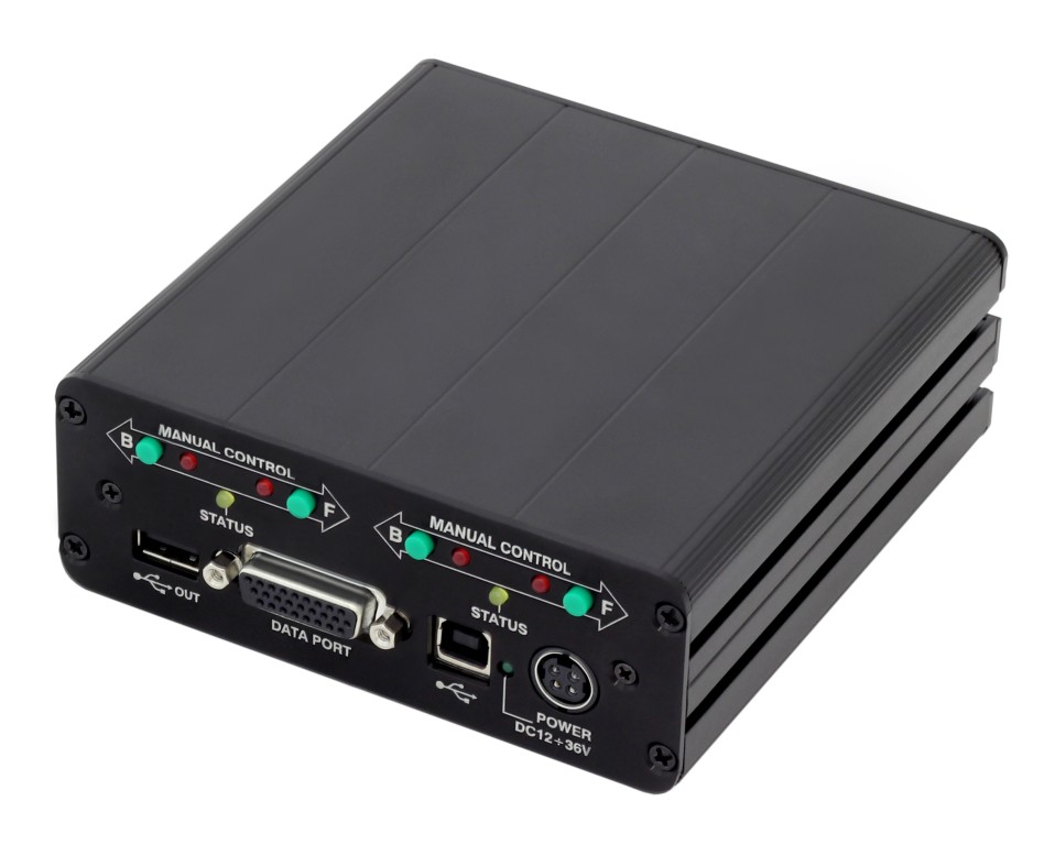
Front panel of the two-axis controller model 8SMC5-USB-B9-2
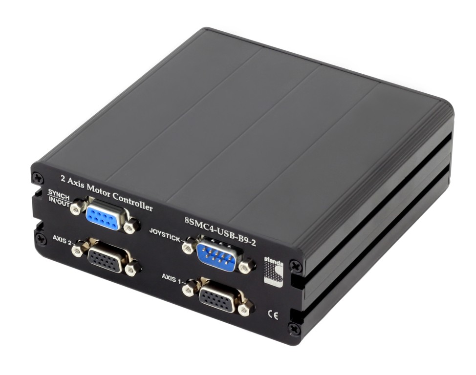
Rear panel of the two-axis controller model 8SMC5-USB-B9-2
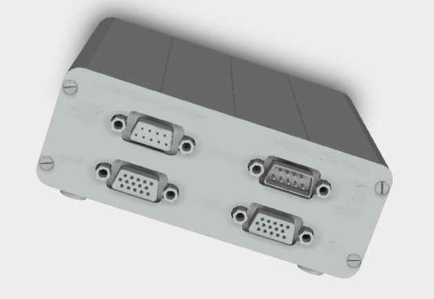
The controller in a metal case of the biaxial variant 3D (model 8SMC4-USB-B9-2)
Two-axis controller model consists of two controller boards in a metal case. Case dimensions are 122 x 48.5 x 124 mm. Front panel contains power supply connector, USB-B data connector, supplementary two-axis system connector, USB cascade connector, and power LED. The cascade USB-A output connector is used to connect several two-axis cases in line terminated with either one-axis or two-axis case. This way a required number of axes can be connected to the computer with a single USB cable. The front panel also contains status LED, left and right limit switch LED, left and right movement buttons for each of the two controller boards of the two-axis system. Rear panel contains positioner connector for each of the two controller boards, a synchronization connector and a joystick connector.
4.1.3.2. Connectors
4.1.3.2.1. Positioner connector
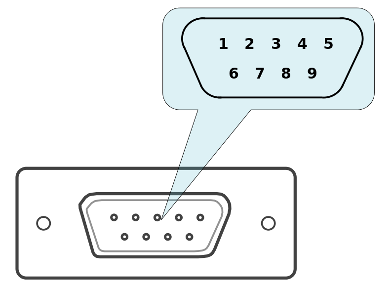
A female DSub 15-pin connector for positioner is mounted on the controller board.
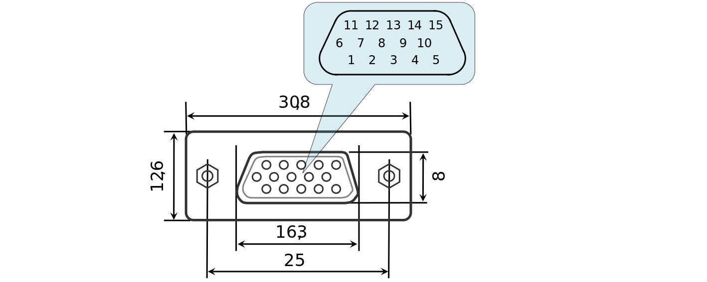
Dimensions and numbers of the pins in DSub connector (front view)
Pins functionality:
- Not phase B of SM or - DC of the motor
- Phase B of SM or + DC of the motor
- Not phase A of SM or - DC of the motor
- Phase A of SM or + DC of the motor
- 5V / up to 100mA stabilized output for encoder power supply
- One-wire interface for positioner identification (for Standa hardware only)
- Logic ground for limit switches, encoder, etc.
- 2nd limit switch
- 1st limit switch
- Encoder channel A
- Encoder channel B
- Revolution sensor input
- NC for 8SMC4
- NC for 8SMC4
- NC for 8SMC4
Note
Outputs 1 & 3 and 2 & 4 must be connected together for proper DC motor function if the nominal current of the motor is higher than 3A.
Warning
Plugging in/out the motor to the controller is not recommended while motor windings are under voltage.
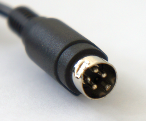
4.1.3.2.2. Power supply connector. 1 and 2 axes system
One- and two-axis controller models in metal cases use Kycon 4-pin DC power connector (part number KPPX-4P, www.kycon.com).
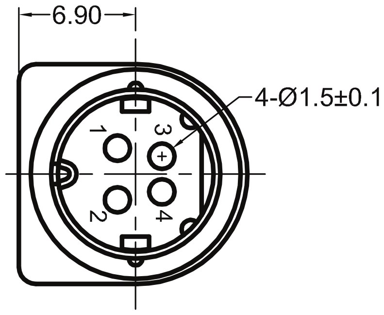
Pinout:
- Power, "-".
- Power, "+". 12-36V.
- Power, "-".
- Power, "+". 12-36V.
Important
Never supply the power to the controller and do not plug it to power connector if you are not confident that your power supply parameters conform to the requirements. Never attempt to plug the power supply to the controller if you are not sure power supply unit and controller connectors are compatible! The acceptable connection parameters are described in Safety instructions.
Important
Hot-swapping or unreliable connection of the power supply connector MF-4MRA may damage the PC and/or the controller. For more details please refer to Safety instructions.
4.1.3.2.3. Data connector. 1 and 2 axes system
Controllers in metal case connect via USB type-B connector.
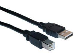
USB-A - USB-B cable
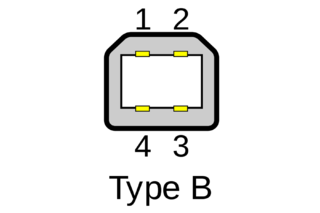
USB type B connector
| Pin # | Name | Wire colour | Description |
|---|---|---|---|
| 1 | VCC | Red | +5V DC |
| 2 | D- | White | Data - |
| 3 | D+ | Green | Data + |
| 4 | GND | Black | Ground |
Warning
Use verified USB cables only! Damaged or low-quality USB cable may cause improper controller operation, including motor rotation errors and errors of device recognition by PC operating system. Short cables with thick wires and screening are ideal for sustainable connection.)
4.1.3.2.4. Joystick connector
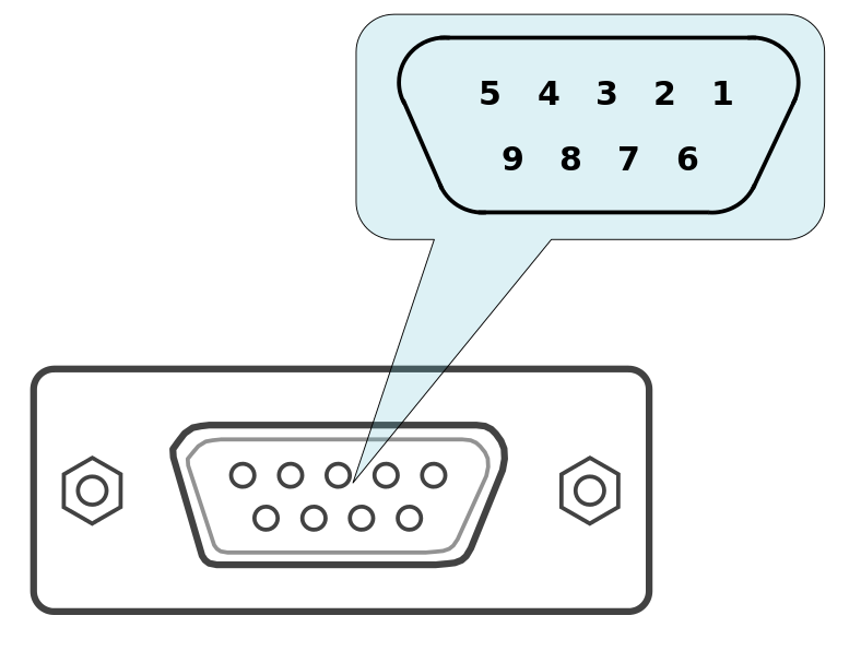
A single-axis or two-axis controller model may contain a 9pin DSub male joystick connector.
Pinout of the joystick connector, front view
Pinout:
- BUT_R_1, right button input, axis 1.
- Joy_2, analog 0-3V joystick input, axis 2.
- GND, common ground.
- BUT_R_2, right button input, axis 2.
- GND, common ground.
- Joy_1, analog 0-3V joystick input, axis 1.
- 3.3V output.
- BUT_L_1, left button input, axis 1.
- BUT_L_2, left button input, axis 2.
Note
If the connector belongs to a single-axis model, then pins 2, 4, 9 are not used.
Note
Unused pins of the internal connector do not require any additional connection or pullup/pulldown. Simply do not use them.
Important
Analog Joy, Pot inputs are designed to work with LESS THAN 3V voltage. Do not apply higher voltages, including 3.3V, to these inputs, as it can break all analog controller inputs and lead to the controller or motor failure.
4.1.3.2.5. Synchronization connector
A single-axis or two-axis controller model may contain a synchronization and magnetic brake 9pin DSub female connector.
Pinout of the connector, front view
Pinout:
- Magnetic brake output, axis 1, +24V
- Synchronization input, axis 2, 3.3V logic
- Synchronization input, axis 1, 3.3V logic
- Unused
- GND, ground pin
- Magnetic brake output, axis 2, +24V
- Synchronization output, axis 2, 3.3V logic
- Synchronization output, axis 1, 3.3V logic
- GND, ground pin
Note
If the connector belongs to a single-axis model, then pins 2, 6, 7 are not used.
Note
In case magnetic brake control board is not connected, then pins 1 and 6 are not used.
Note
Unused pins of the internal connector do not require any additional connection or pullup/pulldown. Simply do not use them.
4.1.3.2.6. Supplementary two-axis system connector
Two-axis controller model contains a HDB-26 female DSub connector.
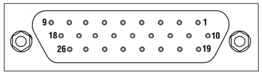
Pinout of the supplementary HDB-26 connector, front view
Pinout:
- RX_2, serial port input, axis 2
- NC, not used
- TX_2, serial port output, axis 2
- GND, ground
- NC, not used
- NC, not used
- NC, not used
- RX_1, serial port input, axis 1
- NC, not used
- CLK_1, Clock signal for the external driver, axis 2
- POT_2, analog input, axis 2
- ExtIO_2, input-output pin, axis 2
- DIR_1, Direction signal for the external driver, axis 1
- GND, ground
- +5V
- BRAKE_1, brake control output, axis 1
- CLK_1, Clock signal for the external driver, axis 1
- TX_1, serial port output, axis 1
- DIR_2, Direction signal for the external driver, axis
- BRAKE_2, brake control output, axis 2
- NC, not used
- GND, ground
- NC, not used
- +5V
- ExtIO_1, input-output pin, axis 1
- POT_1, analog input, axis 1