4.1.4. Multi-axis system
4.1.4.1. Enclosure view
Multi-axis version of motor controller is 7U design with handles for setting on usual 19” industrial cabinet. It contains up to 36 controllers boards. Every 4 boards combined together in 1 module. Device dimensions: 445 x 375 x 311 mm.
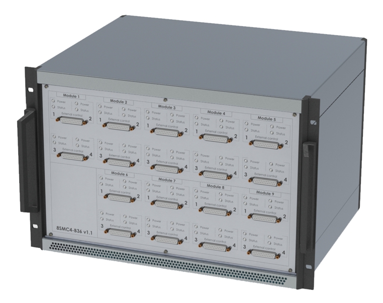
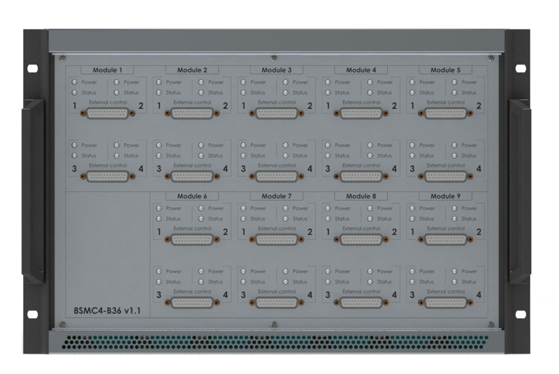
Front pannel divided by 9 parts with titles: “Module 1”, “Module 2”,…,”Module 9”. Every such module contains indication signals “Power” and “Status” for every axis inside module and “External control” connector.
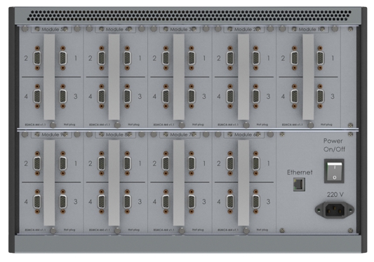
Back pannel contains 220 V connector, Ethernet socket, on/off power button and 4 positioner connectors for every module. Total quantity of position connectors is 36.
Every module can be plugged/unplugged during multi-axis system works. To unplug module it is needed to unscrew the screws with corrugated heads and pull the handle.
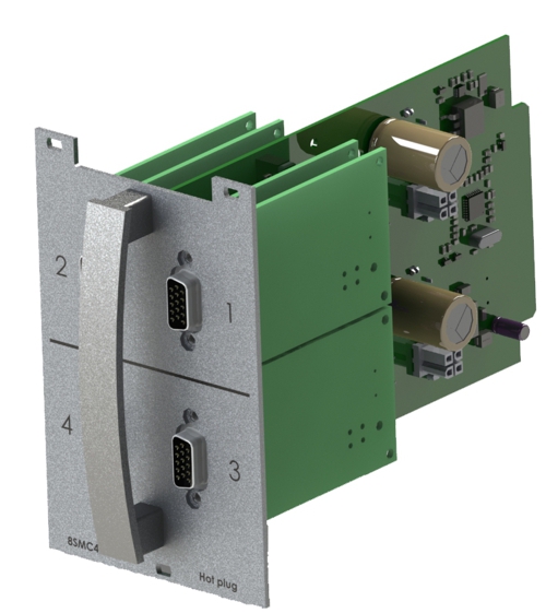
Schematic view of module
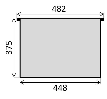
4.1.4.2. Dimensions
Structurally multi-axis system is designed as 7U box with handles for setting on usual 19” industrial cabinet.
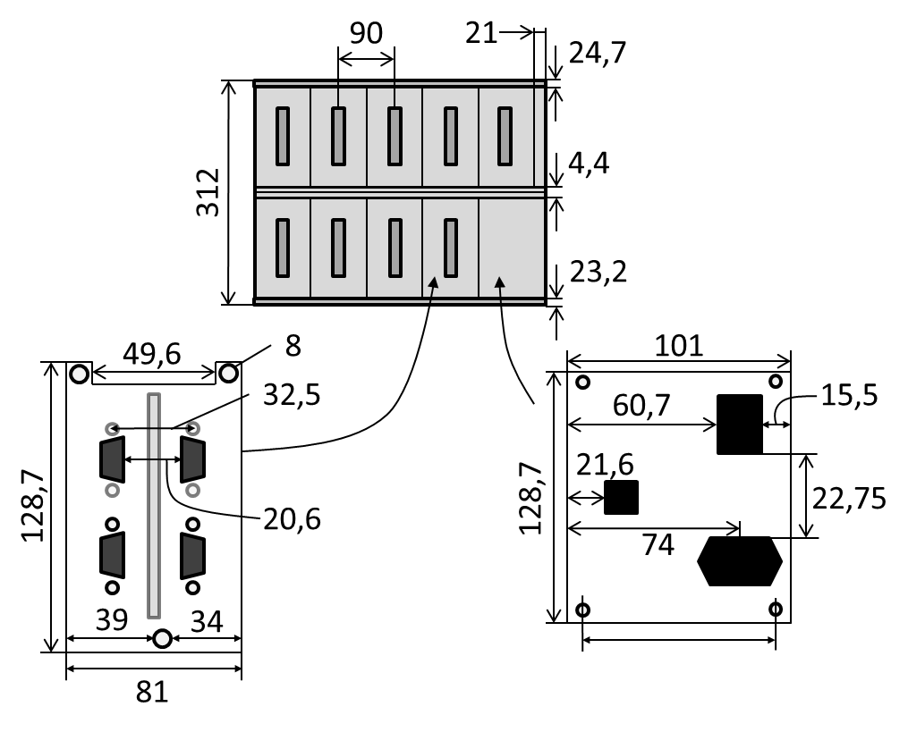
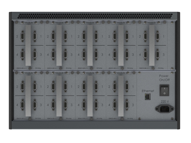
Back view of multi-axis system. View from 220V power connector and control modules side.
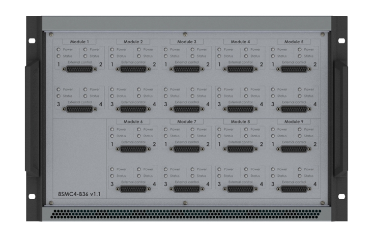
Front view of multi-axis system. View from external connectors side.

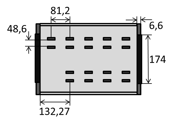
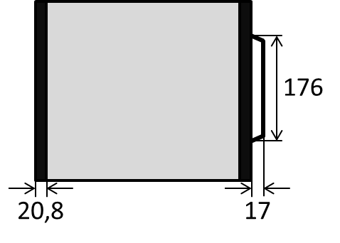
Top view of multi-axis system.
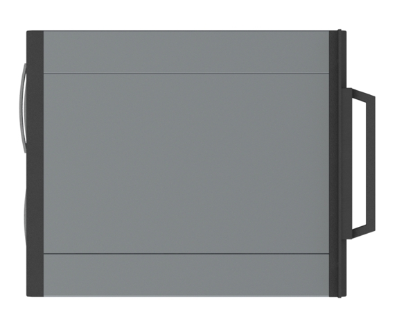
Side view of multi-axis system.
4.1.4.3. Connectors
4.1.4.3.1. Positioner connector
A female DSub 15-pin connector for positioner is mounted on the controller board.
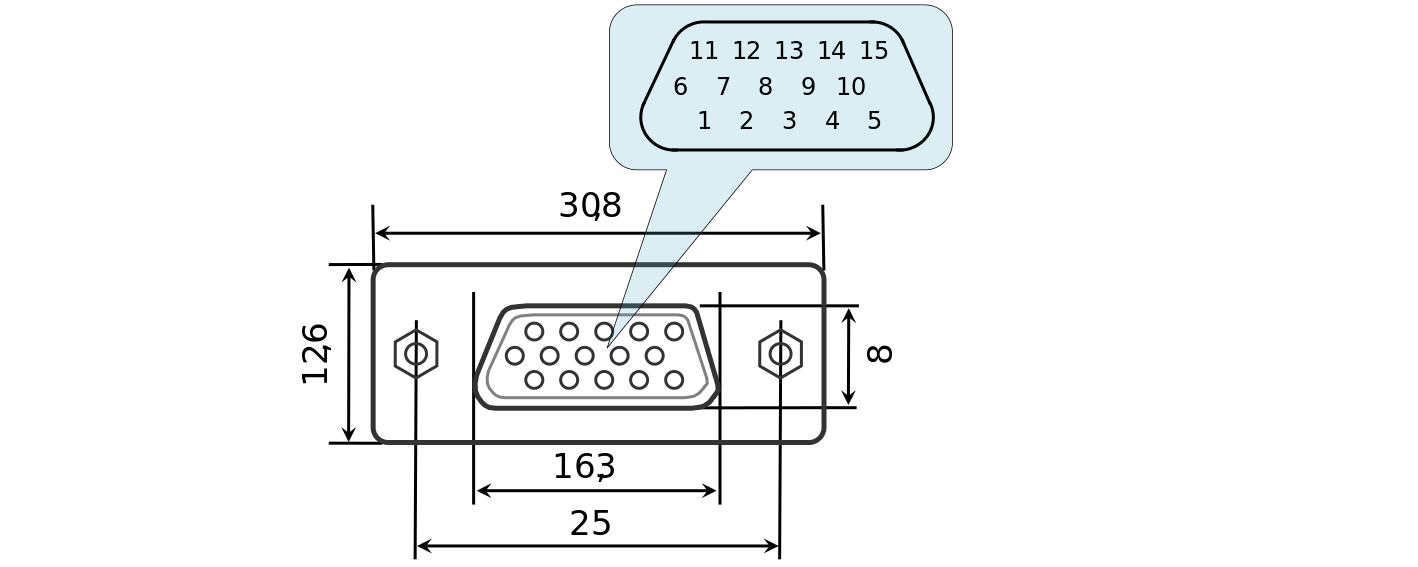
Dimensions and numbers of the pins in DSub connector (front view)
Pins functionality:
- Not phase B of SM or - DC of the motor
- Phase B of SM or + DC of the motor
- Not phase A of SM or - DC of the motor
- Phase A of SM or + DC of the motor
- 5V / up to 100mA stabilized output for encoder power supply
- One-wire interface for positioner identification (for Standa hardware only)
- Logic ground for limit switches, encoder, etc.
- 2nd limit switch
- 1st limit switch
- Encoder channel A
- Encoder channel B
- Revolution sensor input
- NC for 8SMC4
- NC for 8SMC4
- NC for 8SMC4
Note
Outputs 1 & 3 and 2 & 4 must be connected together for proper DC motor function if the nominal current of the motor is higher than 3A.
Warning
Plugging in/out the motor to the controller is not recommended while motor windings are under voltage.
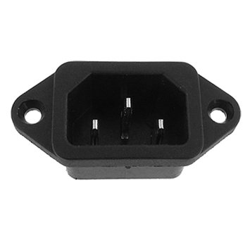
4.1.4.3.2. Power supply connector. Multi-axis system
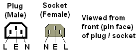
Multi-axis system consumes 220 V via IEC connector.
Pins functionality:
| N | “zero” |
| E | “ground” |
| L | “phase” |
4.1.4.3.3. Data connector. Multi-axis system
Multi-axis system can control up to 36 axes via Ethernet simultaneously. It uses RJ45 connector with “female” type:

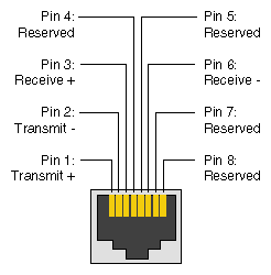
Pins functionality
4.1.4.3.4. Supplementary multiaxis system connector
This connector placed on the front panel of the multiaxis system and named as External control. There are total 18 such connectors. This connectors are useful for control motors by external devices such as joystick or buttons. Also power, status and border indicators are routed to this connector.
Appearance of the front panel
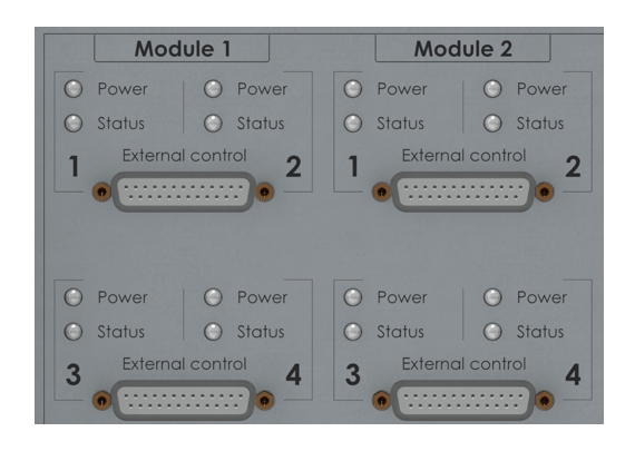
Scaled view of the two modules
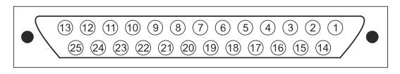
Appearance and pin-numbers of DB-25 connector (front view)
Pin function:
- PWRLED1, power indicator LED of the controller 1
- LEFTEDGE1, left border indicator of the controller 1
- LEFTBUTTON1, left button input of the the controller 1
- JOY1, joystick input of the controller 1
- NC, not connected
- +5VP, output +5V
- SYNCOUT, synchronization output of the module
- GND, ground
- NC. not cnnected
- JOY2, joystick input of the controller 2
- LEFTBUTTON2, left button input of the controller 2
- LEFTEDGE2, left border indicator of the controller 2
- PWRLED2, power indicator LED of the controller 2
- STS1, status indicator LED of the controller 1
- RIGHTEDGE1, right border indicator of the controller 1
- RIGHTBUTTON1, right button input of the controller 1
- NC, not connected
- NC, not connected
- SYNCIN, synchronization input of themodule
- +3V, output +3V
- NC, not connected
- NC, not connected
- RIGHTBUTTON2, right button input of the controller 2
- RIGHTEDGE2, right border indicator of the controller 2
- STS2, status indicator LED of the controller 2
Note
The synchronization output goes to the hi-level state if the synchronization outputs of the all 4 controllers in the hi-level state and the synchronization input of the module in the hi-level state.
Note
If the synchronization input is not connected, it pulls up to the hi-level state by the internal pull-up resistor.