4.5.1. Operating modes indication
4.5.1.1. Controller status
Mode indication is provided in controller. For this purpose one dual-color LED is located on the board.
Green Power indicator shows presence of 3.3 V power supply of controller.
Red Status indicator represents controller operating mode. Simultaneous glowing of both lights looks like yellow glow.
| Flicker frequency Hz | Description |
|---|---|
| Lights don’t glow | the device is shut down, there is no power supply |
| LED is green | the device is broken or the microprogram is not loaded |
| LED is yellow | the device is in Alarm |
| 0,25 | the device is operating but there is no connection with USB from PC |
| 1 | the device is operating, the movement is stopped |
| 4 | the device is operating, with movement |
| 8 | the device is in re-flashing mode |
| 10 | the device is in USB bus reconnecting mode |
4.5.1.2. Indication of limit switches
Multifunctional 20 pin BPC connector is provided with limit switches activity indication. High logic level appears on the corresponding output in the moment of limit switch activity. Active state is determined from limits switches settings (see Motion range and limit switches)
4.5.1.3. Connection diagram
Note
In case of additional LEDs they should be designed for 4 mA operational current. There is no need in additional current limiting resistors. Operational current for typical LEDs is about 2 mA. It is not recommended to use blue and violet LEDs because of their high cut off voltage and as a consequence low brightness.
4.5.1.3.1. Controller board
Indicators Power and Status are duplicated by outputs on the multi functional 20 pin BPC connector with the next scheme of LEDs connection:
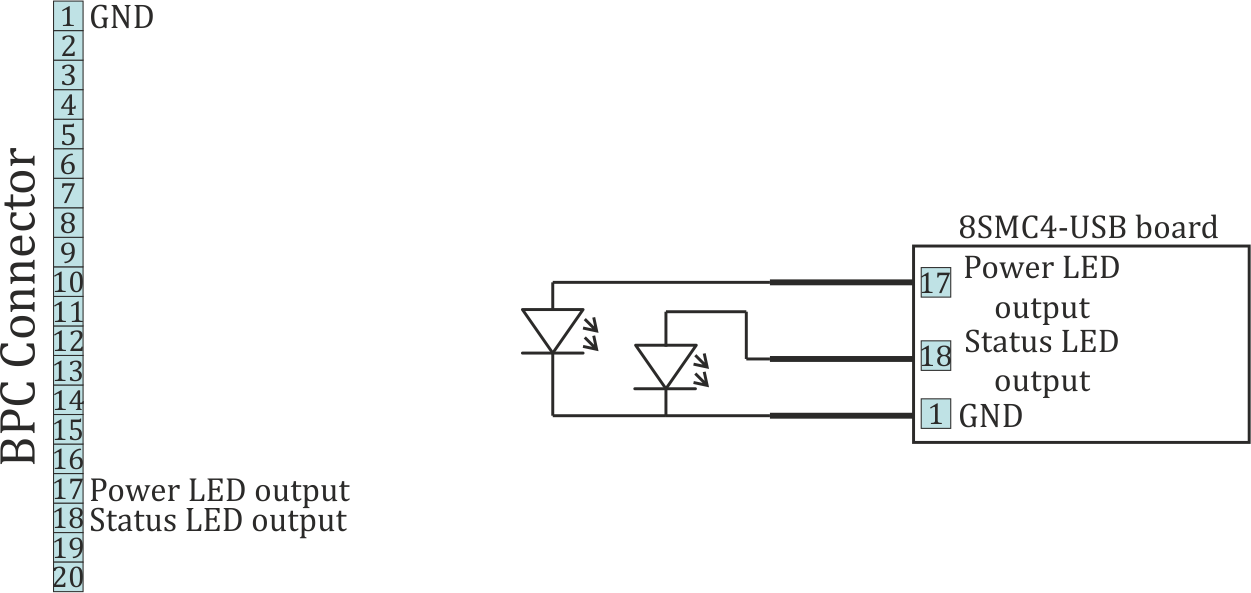
Connection of Power and Status indicators to the controller board
Limit switches are located on the same connector. The connection diagram is shown below. To indicate the limit switches it is convenient to use the LEDs designed for the necessary current.
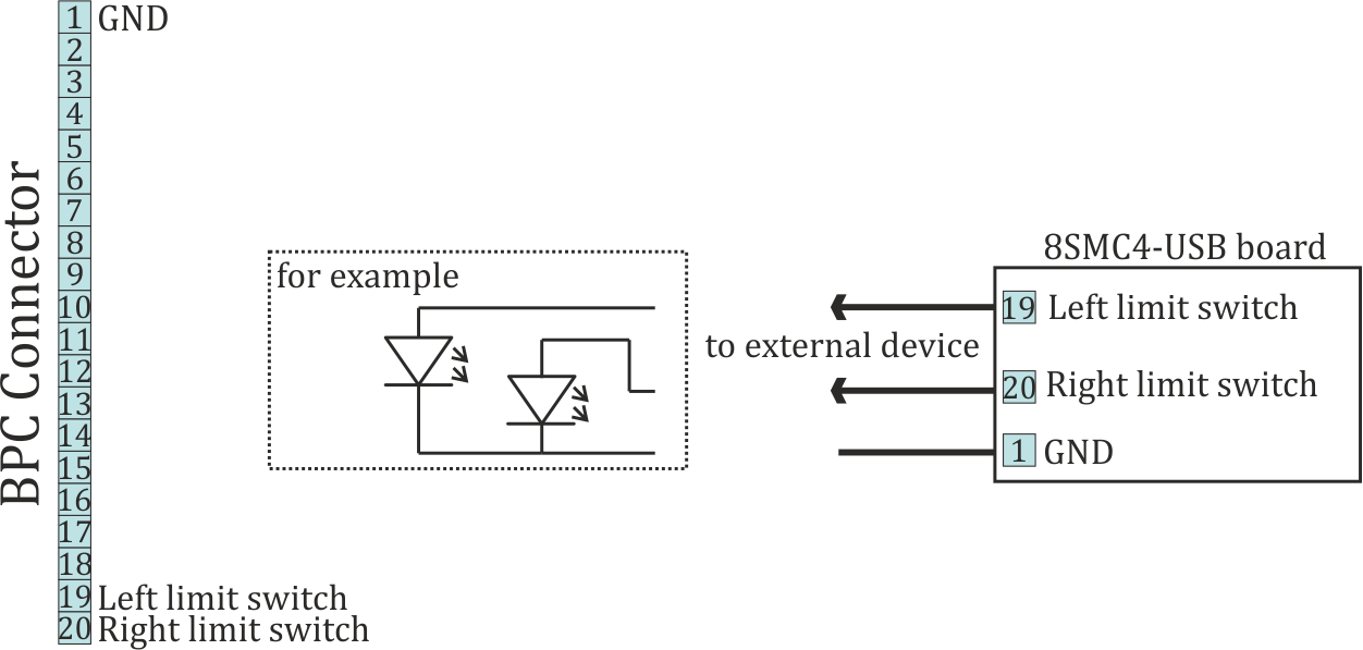
Connection of the limit indicators to the controller board
4.5.1.3.2. One-axis and two-axis systems
LEDs on the front panel of controllers in the box (one-axis and two-axis systems) are indicators for power, status and limit switches, therefore a connection diagram is not required.
4.5.1.3.3. Multi-axis system
In the multi-axis system the signals of indication output to the external DB-25 connector.
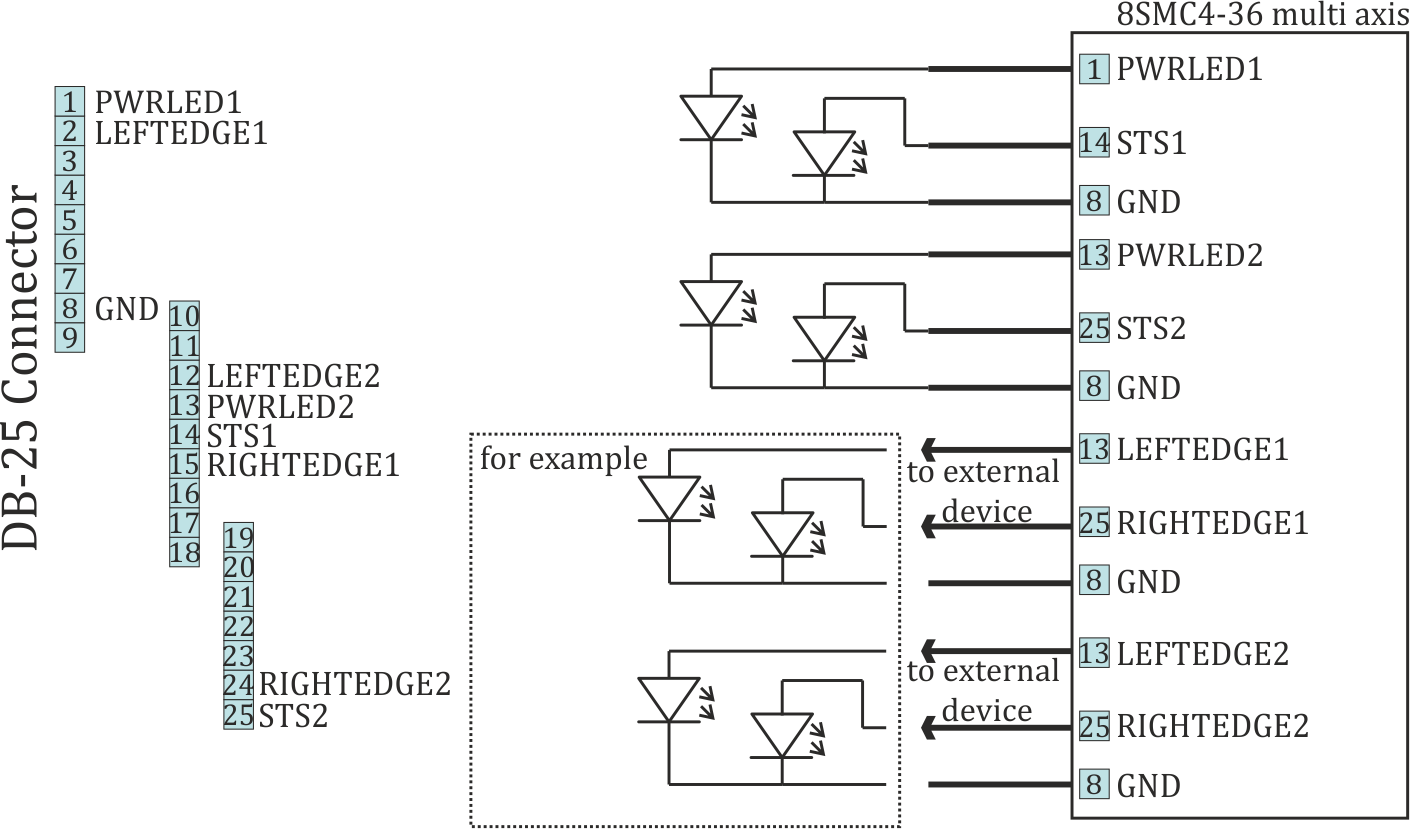
Connection of Power, Status and limit indicators to the multi-axis system