3.5. Calculation of the nominal current
In order to stepper engine gave maximum torque, but it does not overheat, it is important to specify such technical characteristic as the rated current.
The greater a current in the motor winding, the greater the torque at the axis. It is important to remember that with an increase a current flowing through the winding, thermal power released by the motor increases. So the engine could operate for a long time allocated to thermal power (Joule heating) must be less power dissipation. Power dissipation can be calculated on the basis of documentation on the engine.
3.5.1. Calculation based on the parameters of unipolar full step mode
Power dissipation is equal to
where \(R_u\) - the resistance of the winding in unipolar mode, \(I_u\) - current through the winding in unipolar mode, \(n\) - the number of simultaneous windings.
Consider, for example, ST2818M1006. The table in the documentation shows that in full step mode simultaneously running two phase (n = 2) in the unipolar mode, i.e. \(P = 2 R_u I_u^2\). The motor controllers support only bipolar control mode. To switch from a unipolar to a bipolar mode, connect each phase windings in series, the resistance will increase, \(R_b = 2 R_u\), where \(R_b\) - the resistance of the series-connected windings in the bipolar control mode.
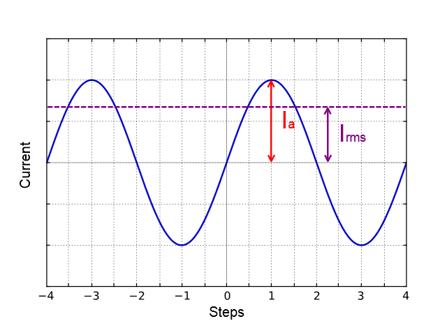
The motor controllers control algorithm is capable of operating in a microstepping mode and maintains the current so that the first winding current varies in function \(I_a \sin(\phi)\), in the other winding current varies in function \(I_a \cos(\phi)\), where \(I_a\) - current amplitude. Thermal power released two windings at any time
It follows from the foregoing that the \(I_a = I_u\).
3.5.2. Calculation based on the parameters of bipolar full step mode
Power dissipation is equal to \(P = n \cdot R_b I_b^2\), where \(R_b\) - the resistance of the winding in bipolar mode, \(I_u\) - current through the winding in bipolar mode, n - the number of simultaneous windings.
Consider, for example, ST2018S0604. The table in the documentation shows that in full step mode simultaneously running two phase (n = 2) in the bipolar mode, i.e. \(P = 2 R_b I_b^2\).
Thermal power dissipated in the motor windings that managed by motor controller, still is
We obtain the equation equating power \(2 R_b I_b^2 = R_b I_a^2\). We find that \(I_a = \sqrt{2} \cdot I_b\).
3.5.3. The relationship with an rms current
Alternating current in each motor winding can be characterized by its rms value in the period
Thermal power of one winding is associated with an rms current through it \(P_1 = R_b I_{rms}^2\). Both windings are identical \(P_1 = P_2\). The total thermal power of the engine that is run by control by motor controller controller \(P = P_1 + P_2 = 2 R_b I_{rms}^2\).
It follows from the foregoing that \(I_{rms} = \frac{I_u}{\sqrt{2}}\), also \(I_{rms} = I_b\).
3.5.4. Setting the nominal current
Motor controller are capable of taking the nominal current value as a current amplitude or as rms. The choice of which way to interpret the input value of the nominal current is determined by the absence or presence corresponding flag ENGINE_CURRENT_AS_RMS in the EngineFlags engine settings structure. When setting the nominal current in XILab should properly specify how the current is interpreted. Motor controllers in this case will provide the maximum torque without overheating the engine.
For all Standa motorized positioners prepared configuration files that contain the specified nominal current as rms. The corresponding flag is set. Thus the engines operate at optimum settings.