3.3. Example of a motor connection
3.3.1. General case
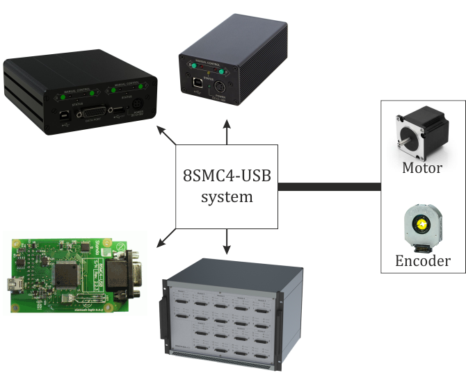
To connect a motor to the controller please refer to positioner connector, and use the scheme of positioner connection:
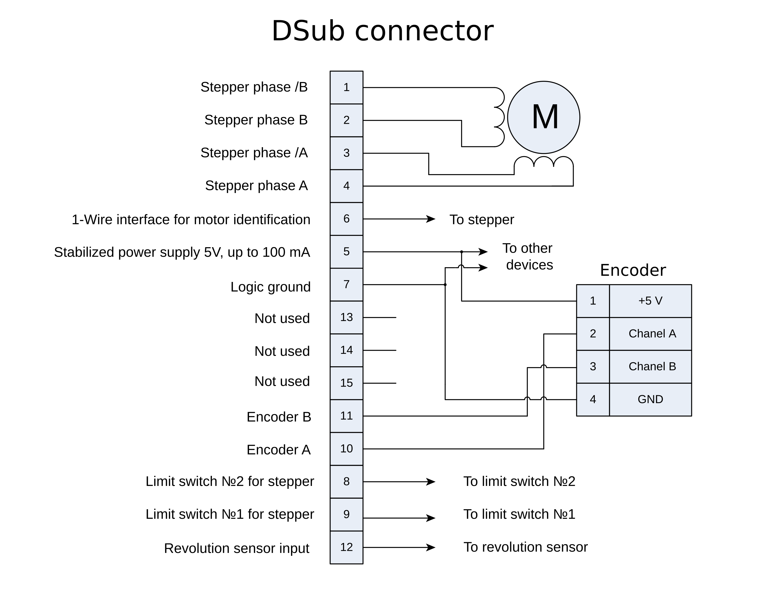
General diagram of positioner and encoder connection using D-sub connector
Note
If A and B encoder channels work in open drain mode, some extra pull-up of encoder outputs to 5V power voltage using the resistors may be required at high rotation speeds in order to provide the maximum signal transmission speed (see Operation with encoders).
3.3.2. Example
Consider the connection of the two-phase stepper motor Nanotec ST5918L3008-B with encoder CUI INC AMT112S-V to controller 8SMC4-USB.
3.3.2.1. Preparation
To get started, we need:
- Motor;
- Encoder;
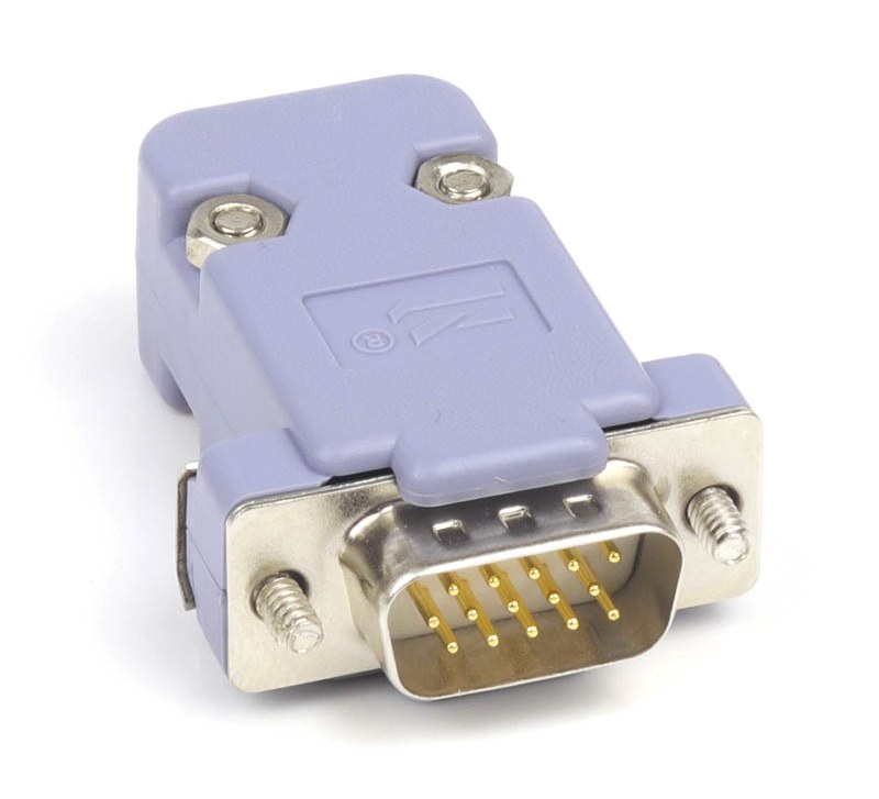
- Pinout of D-SUB connector for 8SMC4-USB;
- Motor datasheet ;
- Encoder datasheet ;
- Soldering equipment: soldering-iron, wires, flux, solder, nippers, heat shrink tubes of different sizes;
- Screws M2.5x6 for fixing the encoder;
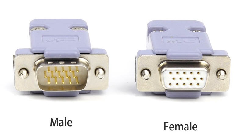
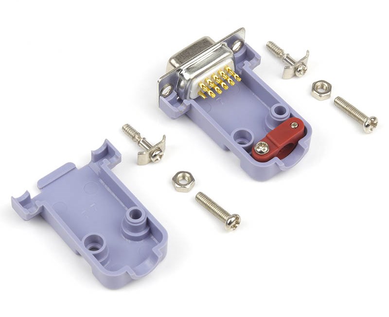
- D-SUB cover + connector (male) and wires for cable manufacturing;
3.3.2.2. Connecting the motor and encoder to the controller
Before you begin, assemble the encoder in accordance with the appropriate instructions.
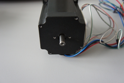
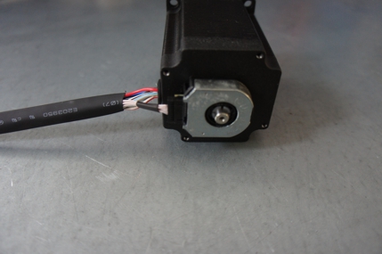
The motor without encoder. Note 2 holes M2.5 to which is usually attached an encoder
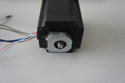
Motor with attached encoder
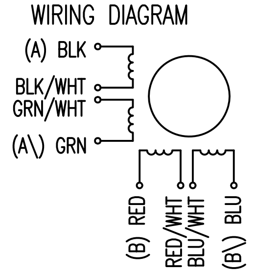
Let us look in the specification of the engine and find the wiring diagram (for Nanotec ST5918L3008-B it is at the bottom right in the specification):
Motor contacts
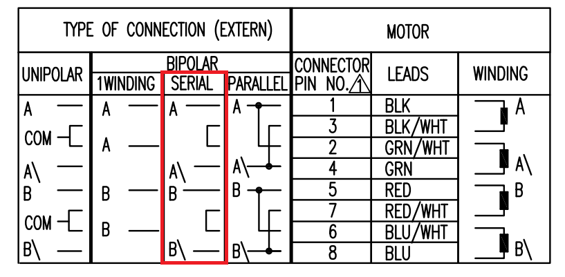
Connection type
There exist serial and parallel winding connection and each type allows to obtain various characteristics for the motor. We will connect the windings in series (red frame on the picture). To do this, wires having two colors BLK/WHT and GRN/WHT, as well as RED/WHT and BLU/WHT must be connected to each other in pairs. Next, you need to put in accordance A, not A, B, not B pins of controller to contacts of motor windings ST5918L3008-B: black, green, red, blue. One winding is a connection of A and not A or B and not B. After the connection between a two-color wire, you will get that one winding of the motor is black - green connection, other is red - blue. Therefore, matching contacts will be the follows: black - A, green - not A, red - B, blue - not B. It can be seen in the picture above Connection type.
To connect encoder, open its datasheet and find 5 contacts on encoder connector: A+ (channel A), B+ (channel B, shifted relative to A by 90 degrees), Z+ (rev counter), 5V, GND. They should be taken from the encoder as 5 separate wires and put together with the wires from the motor as they then go to a connector. CUI INC AMT112S-V encoder has 18 pin input, therefore it is needed to make a cable with the same connector on the end to output necessary signals:
Encoder contacts A+, B+, Z+, 5V and GND corresponds to 10, 11, 12, 5, 7 pins of D-SUB male connector respectively.
For convenience, use the next tables (the number in parentheses indicates pin on the corresponding connector):
| Encoder pin | D-SUB pin |
| A+ (10) | Encoder A (10) |
| B+ (8) | Encoder B (11) |
| Z+ (12) | Revolution sensor input (12) |
| 5V (6) | Output 5V, 100 mA (5) |
| GND (4) | Logical ground (7) |
| Motor pin | D-SUB pin |
| A (BLK) | phase A (4) |
| not A (GRN) | phase not A (3) |
| B (RED) | phase B (2) |
| not B (BLU) | phase not B (1) |
Solder the above contacts to D-SUB male connector:
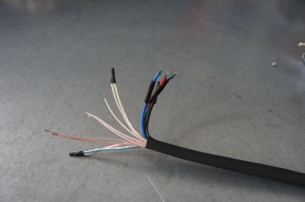
The wires from the motor and encoder in a heat shrink tube. Note the presence of small heat-shrinkable tubes for wires going to the motor windings (BLK, GRN, RED and BLU), as well as two-colored wires joined together (BLK/WHT and GRN/WHT, RED/WHT and BLU/WHT). The thin wires are an encoder contacts (5 pcs).
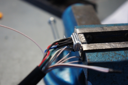
Soldered contacts of the motor windings
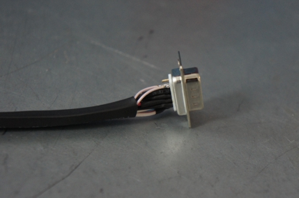
Ready cable from the motor with the D-SUB connector on its end
Recommendation: use heat shrink tubes of a small diameter (2-3 mm) while soldering contacts to D-SUB connector, and large diameter to skip through them all the wires coming from the motor and encoder. Put them before soldering.
Put D-SUB connector into the cover
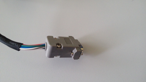
Now you can connect it to 8SMC4-USB
Description and profile settings are given in the next chapter Manual profile setting.