4.3.5. Operation with encoders
4.3.5.1. Application of encoders
Encoders are designed for creation of accurate and fast feedback according to the coordinate for all the electric motor types.The feedback is performed by the motor shaft position, by stage’s linear position, by the motorized table rotation angle or by any other parameter related to the shaft position and measured by using the two-channel quadrature encoder complying the requirements described in Specifications chapter for the appropriate controller type. Controller 8SMC4 supports only single-ended encoders.
Warning
Auto-detect works only with 3.3V and 5V (with error 0.2V) encoders
4.3.5.2. What is quadrature encoder?
Encoder is a mechanical motion sensor. The quadrature encoder is designed for direct detection of the shaft position. The sensor transmits the relative shaft position by using two electric signals at CH A and CH B channels shifted relative to each other at 1/4 of period.
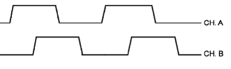
The signals at CH A and CH B outputs of quadrature encoder
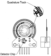
An optical quadrature encoder mechanics
An optical quadrature encoder mechanics is shown at the figure above. There are two optocouplers used. The operational principle of an optocoupler is as following: a LED and a detector are arranged opposite to each other from different sides of a disc. The optocoupler opens when disc’s “window” coincides with the detector (the outgoing signal is logic zero). The outgoing signal is logic one if the detector is closed by opaque part of the disc.
Number of steps per revolution (CPR) is the main parameter of the quadrature encoder. The standard resolution values for encoder are from 24 to 1024 CPR. Each period of signal alteration is interpreted by 1, 2 or 4 codes which is corresponding to X1, X2 and X4 operating modes. This controller uses the most accurate X4 mode. The maximum frequency of each encoder’s signal depends on the applied encoder itself, since for 200 kHz in X4 mode the controller can read up to 800,000 encoder counts per second.
4.3.5.3. Controller’s features
There are two operating modes with encoder available for the controller:
- the encoder is used as the main position sensor (this is the main operating mode for DC motors and the optional one for stepper motors).
- slippage, backlash or steps loss detection (the recommended mode for joint operations with stepper motors, in case the encoder is not used as a primary position sensor, see more).
4.3.5.4. Driving encoder mode
This is the mode when all parameters of the engine including position and velocity are measured directly by the encoder and are denominated basing on counts of encoder. The position is displayed directly in the encoder counts, the speed is denominated in RPM (revolutions per minute). The speed is calculated by the controller basing on the speed alteration data as well as on the number of encoder pulses per one complete revolution of the motor shaft that are displayed in feedback configuration block at the Settings of kinematics (Stepper motor), (DC motor) folder. Note that in the case of DC motor the speed maintaining mode, the mode of movement to the predefined point as well as all their derivations use PID control algorithms and the appropriate settings are required. The driving encoder mode optimizes stepper motor control, this leads to noise reducing and facilitates a stable passage of the resonant speeds with no risk of steps loss when the coordinate flounders and the recurrent calibration is required.
New motor control algorithm is included in the latest firmware. The algorithm add encoder close-loop feedback suppressing motor oscillations and acoustic noises. It makes almost all motors several times faster without any step loss. It all comes with a free update of firmware and software. The new algorithm is available with firmware 3.9.16+ which can we downloaded ´from our website <http://files.xisupport.com/Software.en.html#>`_ or updated through XiLab. Use XiLab 1.13.13+ and set Feedback to Encoder on the Device -> Stepper motor page. Note, that position is in encoder counts now.
4.3.5.5. Encoder connection
The encoder is connected to the controller via D-SUB 15 pin connector, which is in all systems (controller board, one-axis and two-axis in box
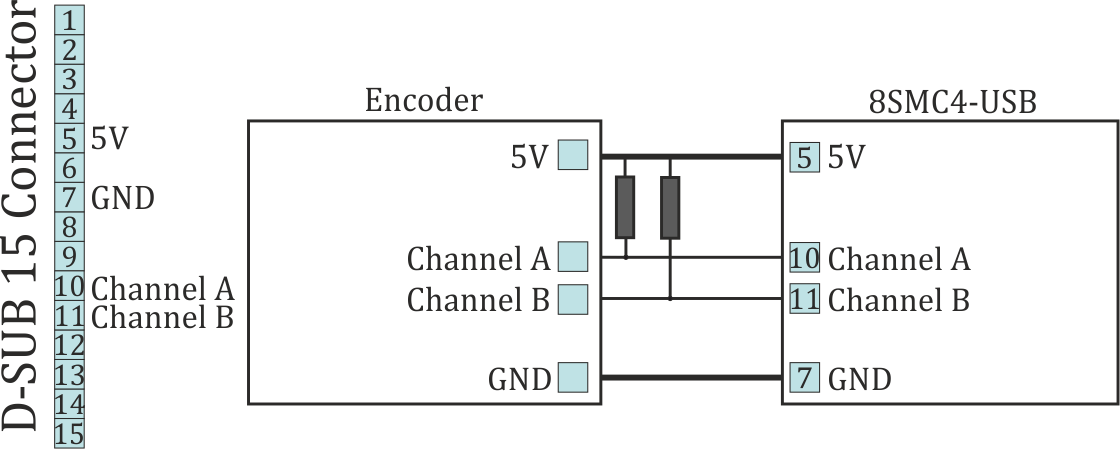
The diagram of single-ended encoder connection using D-SUB 15 pin connector.
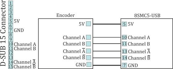
The diagram of differential encoder connection using D-SUB 15 pin connector.
See also the Example of a motor connection chapter.
Warning
Encoder inputs of the controller internally pulled up to logic one by using the 5.1kΩ resistors. Frequently encoder outputs are of “open collector” type equipped with internal pull-up resistor. During the data transmission they provide good characteristics while passing from higher logic level to lower. However, the pass from logic 0 to logic 1 is more graduate. It passes through the RC circuit formed by pull-up resistor and cable capacitance. This is the most important thing if the cable is long (up to 5 meters). If the internal pull-up is not sufficient, the pull-up resistor with r=1.5kΩ may be added for every +5V to each output in order to improve the transmission speed parameters; before doing that please check if the open collector of the encoder can transmit 5mA current. The resistors insertion diagram is shown above. The maximum operating speed for quadrature encoder may be increased by adding a push-pull driver with the outgoing current over 10mA to its output, providing quick 0 - 1 and 1 - 0 transmission edges.