4.3.1. Supported motor types
Currently the controller supports stepper and DC motor types. The parameters of supported motors are described in Specifications chapter.
4.3.1.1. Stepper motors
Rated current is the main parameter of the stepper motor. The rated current is adjustable at the Settings of kinematics (stepper motor) section.
Important
The motor will gradually overheat and get physically damaged if rated current is exceeded. Make sure that the rated current value is set according to the used stage. All the settings are proper in default stage profiles.
Step division mode is another important parameter. In full step operation, the motor moves through its basic step angle (for example, a 1.8° step motor takes 200 steps per motor revolution). Microstepping can divide a motor’s basic step up to 256 times. Microstepping improves low speed smoothness and minimizes low speed resonance effects.
The following step division options are available:
- 1 (full) step
- 1/2 of the step
- 1/4 of the step
- 1/8 of the step
- 1/16 of the step
- 1/32 of the step
- 1/64 of the step
- 1/128 of the step
- 1/256 of the step
The microstep mode is set either on Settings of kinematics (stepper motor) page or by motor adjustment commands. See the Communication protocol specification and the description of the related functions in the Programming guide chapter.
Note
The controller always uses the internal step division value equal to 1/256. If the user selects a coarser step division, the software will display only the multiple of the coarser step division positions and both adjustment and transmission are possible only in that coarser step division mode. This is done for compatibility with both obsolete and actual software operating with small multiples of the step division values. On the other hand, operations with the largest step division value provides the most smooth and silent rotation at the smaller speed values.
The number of steps per revolution is the another direct parameter of the stepper motor. This setting does not affect the rotation but is used in slipping control block or with motors with the encoder feedback.
Note
The controller supports stepper motors with feedback sensor - encoder. The encoder can be used as the main position sensor (more info) and as the slippage, backlash or steps loss detector (more info). Using the encoder facilitates a stable passage of the resonant speeds without movement disruption.
4.3.1.2. DC motors
Unlike stepper motors, controlling DC motors requires feedback. Currently only encoder is supported as a feedback sensor.
Main DC motor parameters are maximum current and voltage, which can be set on Settings of kinematics (DC motor). Main encoder parameter is counts per revolution.
Important
The motor will gradually overheat and get physically damaged if rated current is exceeded. Make sure that the rated current value is set according to the used stage. All the settings are proper in default stage profiles.
Important
Setting wrong value of encoder counts per revolution will lead to the controller being unable to maintain speed correctly. In some cases it may lead to stage or reducing gear failure.
DC engine is controlled by the PID regulator. Please carefully read PID-algorithm for DC engine control before you start working with it.
Important
Wrong PID regulator settings might lead to stage failure. All supplied profiles are preset with correct PID settings. It is not recommended to alter these settings unless absolutely necessary.
4.3.1.3. Engine selection criteria
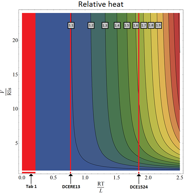
Pulse-width modulation (PWM) is a widely used way to control winding’s current in different motor types. It leads to current oscillations at PWM switching frequency (so-called “current ripple”). Current ripple’s amplitude depends on motor characteristics like its winding inductance and resistance. Motor can heat up more than it is expected with nominal current due to current ripple, i.e. \(\frac{P_{real}}{RI_s^2} > 1\). There is \(RI_s^2\) - power dissipated by \(I_s\) (stabilization current), \(P_{real}\) - real power, dissipated in motor. For overheating estimation we recommend to use this graph:
| Motor | RT/L |
|---|---|
| 20 | 0.19576 |
| 28 | 0.07253 |
| 28s | 0.07168 |
| 4118L1804R | 0.02715 |
| 4118S1404R | 0.02844 |
| 4247 | 0.0273 |
| D42.3 | 0.0223 |
| 5618 | 0.0146 |
| 5618R | 0.0146 |
| 5918 | 0.0116 |
| 5918B | 0.012 |
| VSS42 | 0.029 |
| VSS43 | 0.0256 |
| ZSS | 0.04248 |
| DCERE25 | 0.2106 |
The motor’s overheat is determined by this sequence:
- \(\frac{RT}{L}\) calculation. There is \(R, L\) - resistance and inductance of motor winding (refer to the motor documentation). \(T\) - PWM period time. It’s value should be 51.2 us for stepper motors and 25.6 us for DC motors.
- \(\frac{V}{RI_s}\) calculation. This parameter shows power voltage excess under nominal voltage. There is \(V\) - power voltage,:math:R - winding resistance, \(I_s\) - stabilization current.
- Overheat definition. After first two steps point can be plotted at the graph. Now we should define the region, which corresponds to overheat degree. For example, the region between 1.1 and 1.2 corresponds overheat value between \(1.1 * RI_s^2\) and \(1.2 * RI_s^2\).
There is DCE1524 overheat calculation example:
- \(T\) = 25.6 us
- \(R\) = 5.1 Ohm
- \(L\) = 70 uH
- \(\frac{RT}{L}\) = 1.86
Now we can draw vertical line corresponds this value (look at graph) and find out overheat with different power voltages. Let’s assume \(I_s\) = 500 mA. Nominal voltage in this case is \(R *I_s\) = 2.55 V. If power voltage exceeds nominal more than 5 times but less than 10 times DCE1524’s overheat will be between 1.5 and 1.6. Motor overheats about 1.65 times with 30 V of power voltage.
All the major engines and their parameters have been marked in RT/L values for some motors.