3.4. Manual profile setting
3.4.1. Introduction
All necessary parameters are set after motor connection (see Example of a motor connection where the Nanotec ST5918L3008-B motor connection is described). There we will consider the setting of the profile for Nanotec ST5918L3008-B stepper motor.
3.4.2. Getting started
- Install and run XiLab (see Overview and getting started).
- Load the profile with default settings. To do this, open Settings -> Restore from file … and select xilabdefault.cfg file from XiLab folder.
3.4.3. Nominal current setting
Initially, it is needed to set a correct current in motor windings:
From the specification find the phase current 2.1 A - this is the maximum current for the motor in case of serial winding connection:
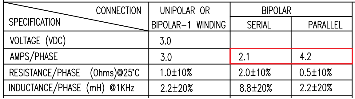
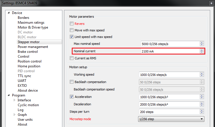
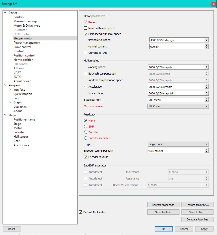
Being in the Settings window, open Stepper motor tab. There are such parameters as rotational speed, acceleration, driving mode, etc. (see Settings of kinematics (stepper motor) for additional information). In Motor parameters-> Nominal current field you should specify the value of the phase current not exceeding 2.1 A:
3.4.4. Basic parameters setting
- In the Working speed field we will specify a rotation speed. The recommended speed is not more than 1000 s/sec at the first start. In the same window you should type Max Nominal Speed (5000 s/sec is reasonable value for majority of motors and motorized stages) and mark Limit speed with max speed. This setting is necessary to limit the motor speed since some mechanical systems can be designed for low speed, and fast rotation can lead to severe wear of motor/stage mechanics.
- In the motor specification we find the number of steps per rotation. For our motor this value is equal to 200 steps. Specify it in the Steps per turn field. Usually, the value of one pitch in degrees is listed in motor description, on the basis of which you can calculate the number of steps per revolution, knowing that one revolution consists of 360 degrees.
- Make sure that movement to the right from the main window of XiLab corresponds to the movement to the right of the stage. If not, then check the box Reverse field Stepper motor -> Motor parameters.
3.4.5. Hardware limit switches setting. Homing.
Note
This section describes the using of motorized stages with hardware limit switches. If your system is not provided with hardware limit switches, it is recommended to disable stop by limit switches in settings. To do this, unmark Stop at right border and Stop at left border in Borders tab.
There are positioners with limited (translators) and an unlimited range of motion (rotators). The limitation of movement range can be done by position or with limit switches using. When you work with translators if its limit switches are configured incorrectly there exists a risk to break down mechanics, since moving part can try to go out of motion range. Rotators do not have such problem. Moreover, it should be kept in mind that rotator may have only one limit switch.
To work with limit switches you must specify which one will be left and right. Sometimes it is unknown in advance and we only know that both switches are connected and fire if the corresponding limit of the motion range is reached. The stage jam is possible if the limit switches are configured improperly. Therefore, the controller supports just a simple detection of incorrectly configured limit switches, shutting down the movement on both of them. Please make sure that:
The stage is far from limit switches;
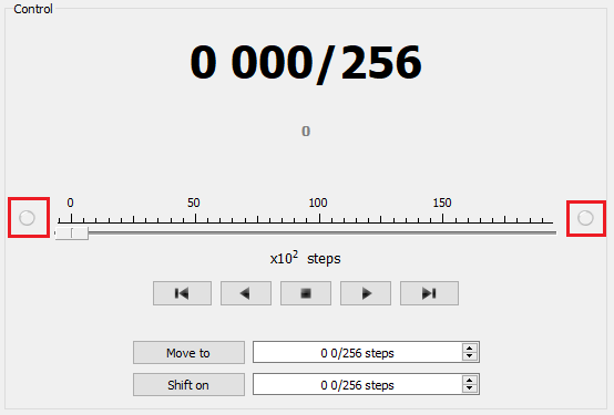
Switches polarity is configured correctly (limit switches indicators are off in the main window of XiLab). In the case of incorrect settings, change their polarity (Borders -> Pushed position), indicators should go out.
Shutdown mode is activated on both of limit switches (Stop at right border and Stop at left border are marked in Borders tab).
Mark the flag detecting improper connection of limit switches Border misset detection in Borders tab.
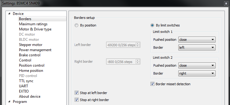
Tab with limit switches settings
Controller can switch to Alarm state after false limit switch response, if Enter Alarm state when edge misset is detected is enabled in Maximum ratings tab. It is recommended to enable it. Start the movement in any direction from the main window of XiLab up to Alarm state or stopping by the limit switch. When an Alarm occurs you need to reverse limit switches by changing Borders->Border with reversed values in the Stepper motor tab.
Warning
The protection against mistaken limit switches connection doesn’t guarantee the complete solution of the problem, it only makes the initial configuration procedure easier. Don’t start the movement with mixed up limit switches if any of them is active, even if the protection is on.
There are still two ways to determine which of the limit switch is right and which is the left:
- You need to know how each of the limit switches is connected to the positioner. When loading a profile with the default settings, switch connected to pin 9 of the D-SUB connector is considered as left, while switch connected to pin 8 - as right. Their location relative to the positioner is configured in the fields Limit switch 1 and Limit switch 2 (see screenshot above). Start the system at the low speed (<100 steps/s) when it is far away from limit switches. If the direction of movement to the switch in a real setting differs from the expected, change Borders->Border values with reversed in the Stepper motor tab.
- If it is possible to get limit switches activate them and note the correspondence between indicators in XiLab and each particular switch. Then start the system at the low speed (<100 steps/s) when it is far away from limit switches and make sure that the system moves to the right switch. Compare this to what you see in the main window of XiLab. If the direction of movement to the switch in a real setting and in the main window differs, change Borders->Border values with reversed in the Stepper motor tab.
For detailed information refer to motion range and limit switches.
Controller has a useful function called automatic Home position calibration to set the initial position of the motorized stage.
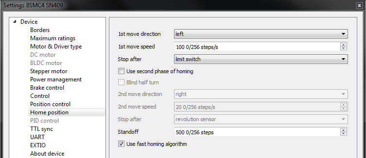
We will consider the most simple configurations with a single phase only. Start from the setting of the 1st phase speed which is approximately 5-10 times lower than Working speed. It is necessary for higher precision of automatic calibration procedure. In the filed Stop after specify the limit switch to make the stage reached one of the limit switches during the calibration (direction is selected in the 1st move direction). In the field Standoff specify number in steps, for which stage must be driven away from the limit switch. Click Ok or Apply.
Note
Standoff value is signed. Positive direction is right. That is, if the auto-calibration procedure is set up on the right limit switch, then in order to move stage away to the left you should type negative value in Standoff field.
- Start the automatic calibration by clicking Go home in the main window of XiLab. The result of it is a movement of the positioner to the specified limit switch with a relatively low speed and the shift away from him to the value specified in the field Standoff.
- After completion of the calibration process, press Zero in XiLab to set the origin of coordinate system for your stage.
- Repeat the calibration process again. The stage must return to the zero position. Please pay attention that there can be slight deviations from zero connected with calibration procedure error.
3.4.6. Encoder parameters setting
Note
This section describes the using of motor with encoder. If you motor without an encoder, the parameters described below can be left unchanged.
Any encoder has Pulse Per Turn - PPT parameter (sometimes it is called PPR - Pulse Per Rotation). For correct operation of the encoder with controller you should enter the number of encoder counts per revolution, which is equal to 4xPPT in the Encoder counts per turn field in XiLab. For example, if your encoder has 1024 pulses per turn, specify 4096 in the Counts per turn:
Start the motor rotation from the main window of XiLab. If everything is configured correctly, the green indicator ENCD will light in the bottom of window. If ENCD has yellow color, you should mark Encoder reverse in the Stepper motor tab. Red color of EDCN points to the problem with encoder position recalculation.
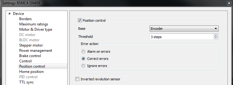
It is possible to activate the position control by encoder. To do this, in the tab Position control mark Position control and specify allowable error in terms of encoder counts in the Threshold field. Then, when a mismatch between position and encoder counts occurs, indicator SLIP will light in the bottom of XiLab main window. Beyond this, if Alarm on errors is marked, the controller will go to Alarm state. Correct errors allows you to start closed loop control, when the difference between real position and encoder position is compensated.
3.4.7. Setting the kinematic characteristics of the controller
In the Stepper motor tab you may specify a necessary acceleration (Acceleration) and deceleration (Deceleration) for your stepper motor. The process of optimal values selection is the next:
- Starting from default values make small shifts (start and fast stop) with gradual Acceleration increase until the movement become unstable and disrupted sometimes. Take acceleration equal to about half of this value.
- The deceleration can be configured about 1.5 - 2 times higher than acceleration.
If in your mechanical system moving to the desired position on the left and on the right is not the same, and there is play, it is possible to eliminate this ambiguity. To do this mark Backlash compensation in Stepper motor and type number greater than play value. The sign of this setting determines the direction of moving to the position. Positive sign means move from the left while negative - from the right. In Backlash compensation speed field set the speed of compensation movement. This value should be low (50 s/sec is enough) in order to avoid “drifting” during backlash compensation.
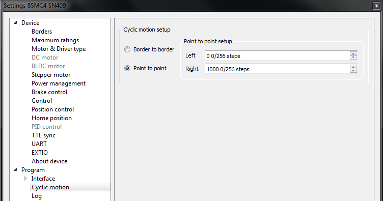
After the basic configuration of the positioner/motor, you can increase working speed. It can be done experimentally like the process of acceleration setting, i.e. you should take its value about 2 times lower than value at which there is unstable movement. To test the stability of the rotation it is recommended to use the function Cyclic in XiLab main window. Make sure that you set it previously.
In the Microstep mode field we recommend to enter the value 1/256.
3.4.8. Working with user units
Often it is uncomfortable to work with the steps and microsteps and more convenient units are preferable. For this reason, the controller can recalculate the coordinates in the usual units, for example in millimeters or degrees. It can be done in the tab User units, where you should specify the size of the step and the corresponding measurement unit. For more information, refer to relevant documentation paragraph.
Configuration of the operating profile complete.