5.2.2. XILab Main window in single-axis control mode
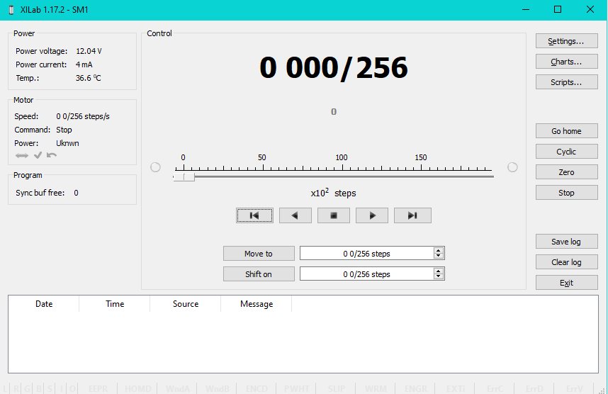
XILab Main Window in General Motor mode
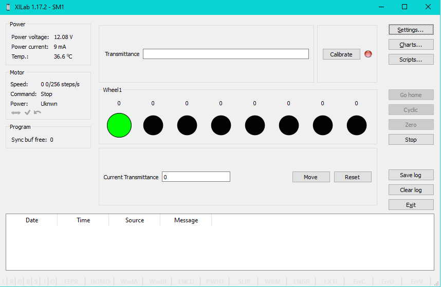
XILab Main Window in Attenuator mode
In the left part of the window in Power and Motor groups of parameters status of the controller and the motor is available. In the central part of the window there is the Control group, containing the elements of motor motion control. On the right there is a group of buttons to control the application as a whole. At the bottom there is a log, which is hidden as the window is resized to its minimum size and a status bar. Below we consider these groups in more detail.
5.2.2.1. Motion Control Unit
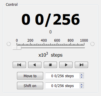
Control Unit
In the central part of the block there is an indicator of the current position. Below it, in case the encoder is enabled, is located an encoder position indicator. In the closed loop mode (see Operation with encoders section) the main and the secondary indicators swap their places.
Below is the Control unit, containing the elements of motor motion control. Let us examine them in greater detail:
5.2.2.1.1. Movement without specifying the final position

Movement control buttons
- The buttons Left, Stop and Right trigger movement to the left without specifying the final position, stop with deceleration any previously started movement, and start the movement to the right without specifying the final position, respectively.
- Button Left to the border will make the motor rotate to the left border of the slider. Right to the border, respectively, will do it to the right edge of the slider.
- When you press and hold the keyboard buttons Right or Left and the slider block has input focus, the movement starts in the direction of increasing or decreasing coordinate. When you release the button the movement stop as if the Stop button on the main window have been pressed.
5.2.2.1.2. Movement to the target point
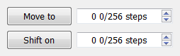
Movement control to the given point
- Move to button starts the process of moving to the given position.
- Shift on button starts the process of shift to a given distance from the target position.
5.2.2.1.3. Target position for motion commands
Commands Move to and Shift on use the target position to calculate the movement. The target position is changed by the following commands:
Commands Stop, Left, Right, Left up to the border and Right up to the border do not alter the target position.
5.2.2.2. Attenuator Control Unit
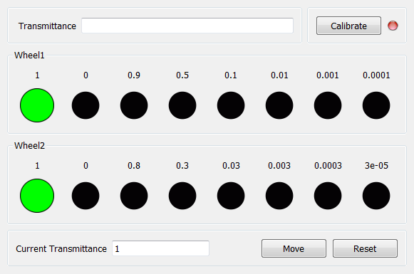
Attenuator Control Unit
At the top of the attenuator control block a Transmittance window and a Calibrate button are located. Transmittance window contains a control to select desired transmittance coefficient. Calibrate button does manual calibration, or location of the initial position, of the attenuator - first it initiates one revolution of attenuator with current controller settings to determine relative position of attenuator wheels and then does Automatic Home position calibration. * Calibrate* button is optional - if the attenuator did not perform the calibration or it was reset, for example by pressing Cancel during movement, calibration will be performed before the next movement automatically.
Attenuator has one or two wheels, each wheel contains 8 optical filters. Below these filters are visualized as bars with circles. Below a Current Transmittance window is located. This window contains trasmittance coefficient which is the closest to desired one that can be achieved with the current filters.
Move button performs movement toward the filters corresponding to the Current Transmittance, that is, the highlighted ones.
Reset button deactivates all filters.
5.2.2.3. Controller and motor status
5.2.2.3.1. Controller Power Supply
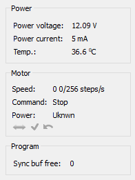
Power group of parameters contains the following indicators:
- Power voltage - voltage supplied to the power module.
- Power current - current consumption of the power module.
- Temp. - Temperature of the controller processor.
If the color of the indicator Power voltage changes to red, it shows that voltage power supply exceeds the allowed value range over the acceptable value. In this case, the controller switches to Alarm state. You can change this parameter in the section Critical board ratings.
A horizontal bar above the field Power voltage indicates that the power voltage exceeds the motor max voltage, you can change this parameter in the section Settings of kinematics (DC motor).
If color of the indicator Power current turns red, it shows that the current consumed by the controller from the power supply is over the acceptable value. In this case, the controller switches to Alarm state. You can change this parameter in the section Critical board ratings.
A horizontal bar above the field Power current indicates that the power current exceeds the motor max current, you can change this parameter in the section Settings of kinematics (DC motor).
If the color of the indicator Temp turns red, it shows that the temperature of the controller board exceeds the acceptable value. In this case, the controller switches to Alarm state. You can change this parameter in the section Critical board ratings.
Important
It is possible to quit the Alarm state after terminating of the events that caused Alarm, provided that the flag Sticky Alarm is not set. If the flag Sticky Alarm is on, use the Stop button to quit the Alarm state.
5.2.2.3.2. Motor status
Motor group of parameters contains the following indicators:
- Speed - rotation speed of the motor.
- Command - the last performing (bold font) or executed (plain font)
controller command. Controller command
appears in black if the flag of the
motion error MVCMD_ERROR is not set, in red otherwise. Can be one of
the following options:
- Move to position - move to the set position
- Shift on offset - offset for a predetermined distance
- Move left - move left
- Move right - move right
- Stop - stop
- Homing - find the home position
- Loft - backlash compensation
- Soft stop - smooth stop
- Unknown - unknown command (it may appear immediately after the controller starts)
- Power - state of stepper motor power supply. Can be one of the
following options:
- Off - motor winding is disconnected and not controlled by the driver,
- Short - winding is short-circuited through the driver,
- Norm - winding is powered with nominal current,
- Reduc - winding is deliberately powered with reduced current relatively to operational one to reduce the power consumption,
- Max - winding is powered with maximum available current, which a scheme with a given voltage supply can output.
Note
You can use the GPIO flag to detect the connected stage
A horizontal bar above the Speed parameter indicates that the speed has reached the maximum speed, which is defined in the Settings of kinematics (DC motor).
5.2.2.3.3. Program status
Program group of parameters contains the following indicators:
- Sync buf free - free slots in the syncin command buffer (see description of ASIA command).
5.2.2.4. Group of application control buttons
- Settings… button opens controller settings, see Application settings.
- Chart… button opens a window with charts, see Charts.
- Scripting… button opens scripting window, see Scripts.
- Go home button searches for the home position, see Home position settings.
- Cyclic button turns on the cyclic motion, see Cyclical motion settings.
Note
The Cyclic command is a constituent command: when invoking Cyclic in XiLab at the controller level the sequence of Move to commands is executed.
- Zero button resets the current position of the motor and the encoder value.
- Stop button sends the command of emergency stop, resets the Alarm state, clears the command buffer for synchronous motion and stops a script if it is running.
- Save log button saves the contents of the log to a file in CSV format (opens a file selection dialog window).
- Clear log button clears the contents of the log.
- Exit button performs safe shutdown, see Correct shutdown.
5.2.2.5. Status bar
Status bar contains current controller status indicators. From left to right these are 7 flags,
- L - Left button state
- R - Right button state
- G - State of external GPIO pin
- B - State of brake pin
- S - State or revolution sensor pin
- I - State of sync in pin
- O - State of sync out pin
and separate indicators
- EEPR - EEPROM is connected.
- HOMD - Controller is in “homed” state (calibration performed)
- WndA - Winding A state
- WndB - Winding B state
- ENCD - Encoder state (none/active/inverted/failed)
- PWHT - Power driver overheat
- SLIP - Motor slip detected
- WRM - Lights up when error is detected the difference between windings resistance
- ENGR - Error response of the engine control action
- EXTI - The error is caused by the input signal
- ErrC - Command error encountered
- ErrD - Data integrity error encountered
- ErrV - Value error encountered