3.1. Overview and getting started
Attention
This manual is universal for 8smc4 and 8smc5 controllers for both uniaxial and biaxial
3.1.1. Introduction
This manual describes the controller installation procedures and getting started with XILab software for Windows 7. The installation on other OSs is described in XILab installation chapter. The detailed controller specifications are described in Specifications chapter. For developing your own applications, please read the Programming guide chapter and download the programming software package from the software chapter.
3.1.2. System requirements
Note
There are only brief requirements in this chapter. For detailed information please read the Specifications chapter.
For successful installation you will need:
PC with USB port

A standard PC with USB port
Make sure that your PC has all of the current Windows updates installed. It will help you to maintain software compatibility. If necessary, please download the latest updates from www.microsoft.com/updates.
Software All necessary software to work with the controller can be downloaded from software page.
USB A - mini-B cable
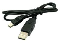
USB-A to mini-USB-B cable
For detailed information about the USB cable please read the data connector or data connector 1 and 2 axes system chapter.
Important
The 8SMC4/5-USB controllers require a minimum voltage of 12 V for proper operation.
The 8SMC4-USB controller can be powered by USB (5V), but the USB power is not enough to turn on the motor.
8SMC4-USB-B8-1
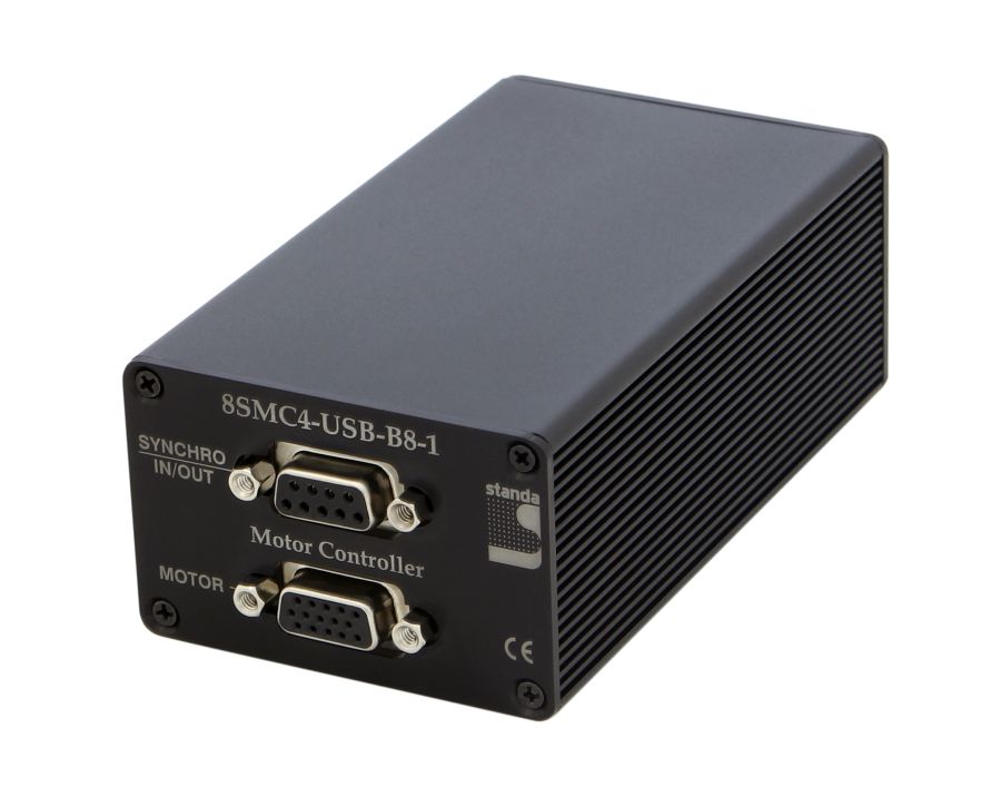
8SMC4-USB-B8-1 One Axis Controller
8SMC4-USB-B9-2
-rear.jpg)
8SMC4-USB-B9-2 Two Axis Controller
The controller appearance may differ from the one shown on the above figure depending on its configuration and version. For detailed information about versions please read the Appearance and connectors chapter.
Positioner or motor
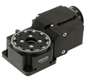
The stepper motor-based positioner
The stepper motor-based positioner used in the operations is shown at the figure. The detailed motor requirements are described in Specifications chapter. If you use your own cables for connecting the positioner to the controller, please refer to positioner connection scheme and the controller’s output connector scheme. For positioners with limited movement range, two limit switches must be used: SW1 and SW2. These pins are used to determine the movement limits.
Power supply
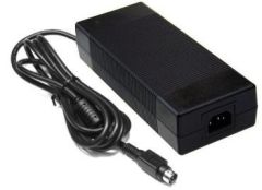
Stabilized power supply unit
Note
- Please use the 12–36V DC stabilized power supply. Too high voltage may damage the controller. For more information please read the Safety instructions chapter. The power supply unit must provide the current enough for sustainable rotation of the motor.
- Please pay attention on the manual supplied with your controller. The more strict power voltage limitation is possible depending on the controller model. Please check the connection of external power supply unit to the controller carefully.
- If controller is supplied inside the metal case, the case must be grounded. If controller is supplied without any body, the grounding circuit of power supply unit is used. For more information please read the Safety instructions chapter.
- If the board is operated without the casing, make sure it lays on the insulating surface and there are no extraneous particles on the board or around it.
3.1.3. Software installation and startup procedures
Make sure that all controllers are disconnected from your PC. The software installation manual is here. The installer file name is “xilab-<version_name>.exe”. It automatically detects whether it is running on 32-bit or 64-bit version of Windows and installs the appropriate version of XiLab. Launch the installation program, the installation window will appear. (The software versions may slightly differ from each other).
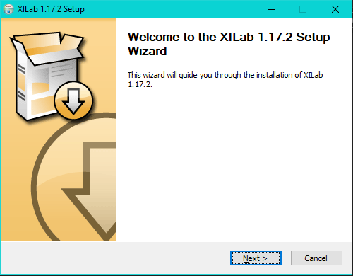
XILab main installation window
Press “Next>” button and follow the instructions on screen. All the necessary software including all drivers, packages and programs will be installed automatically. After installation is finished, the XiLab software starts by default and the following window will open:
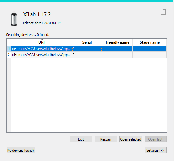
XILab “No devices found” dialogue window
Don’t press any buttons. Connect the positioner to the controller. Connect the stabilized power supply unit to the controller. Ground the controller or power supply unit. Connect the controller to your PC using the USB-A to mini-USB-B cable.
The LED indicator at the controller board will start flashing. The New Hardware Wizard starts working after the first connection of the controller to PC. Please wait until Windows detects a new device and installs all necessary drivers for it.
If the automatic driver installation has failed, please select “No, not this time” in the window being opened and press “Next>” button. Select “Install from a list or specific location (Advanced)” in the next window and press “Next>” again. Browse the software disk supplied with controller and find the *.inf file there or in the XiLab-install-path\driver\ folder and wait until installation is completed.
Go back to XILab “No devices found” dialog window and press “Retry” button. If this window was closed, please go to “Start” menu, select Programs -> XILab X.X.X -> XILab and launch it. The dialog window will open again.
3.1.4. Getting started with XILab software
XILab is a user-friendly graphic interface designed for control, diagnostics and adjustment of motors. It can also be used for easy installation and save/restore of parameters for any type of motors. This chapter describes the startup procedures with XILab software. For complete information please refer to XILab application User’s guide chapter.
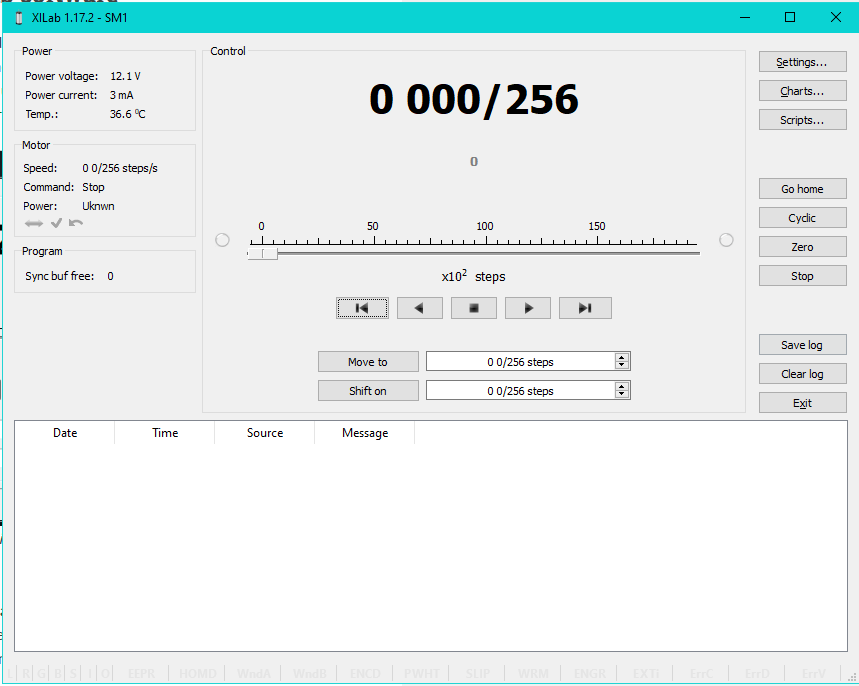
XILab main window
Open “Settings…”, then press “Restore from file…” and select the configuration file for your positioner from the opened C:\Program Files\XILab\profiles\ folder. The values applicable for your positioner will automatically fill all the fields of “Settings…” menu. If the necessary file isn’t found, please refer to the Standa website. If there is still no solution, please leave your request at our customer service website.
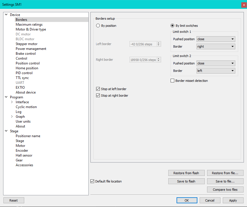
XILab, the Settings menu window
Warning
For the controller to work with stepper motors it is required to properly set up:
- working current,
- displacement limits and limit switches,
- critical parameters,
- limiters,
- power supply mode.
If you decide to configure your controller by yourself, please check these parameters carefully!
Congratulations, your controller is ready for operation!
3.1.5. Functional test
Check if the controller is configured properly by pressing left or right button in the central row of XILab main window control buttons. The positioner has to start moving. Use the central “soft stop” button to stop the rotation. Please pay attention to the power supply parameters of the controller in the Power section. The power voltage, working current and temperature of the controller can be set there.
If Xilab main window is shaded red when the movement was supposed to start, that means that protection was activated and controller entered the Alarm state. This may be caused by incorrect settings, wrong connection of the positioner or controller malfunction. For detailed information please read the Critical parameters chapter.
3.1.6. Control from user applications
Xilab software is a convenient way to control stages connected to 8SMC4-USB controller. However, if you need to control the 8SMC4-USB from your own application, you may do so by using libximc library. Programming guide has several examples in C, C#, Python, Delphi, Java, VB.net, Matlab, LabView programming languages. If all you need is to automate a small number of control steps, then instead of a standalone program you may find it easier to use Xilab scripting language.