4.2.9. Feedback EMF
4.2.9.1. Advantages
- Always supports sinusoidal current form, which ensures silent operation;
- At high speeds, it can dynamically adapt to external loads, current and voltage restrictions (automatically reduces speed);
- At low speeds, it uses frequency control without rotor position control. When the position of the rotor begins to give correct indicators, it switches to the field control mode with feedback on the rotor position. The switching threshold is individual for each engine, it is determined by the quality of the rotor position assessment issued by the observer;
- Does not use the position sensor (encoder);
- It can operate in three modes:
- MTPA - the most economical mode, characterized by a minimum current, but the voltage increases rapidly with the speed of \(I_d=0\);
- FW - the flux linkage step-down mode is active when the set speed cannot be reached within the current voltage using MTPA \(I_d<0\);
- Limit - saturation mode, when movement at the specified speed is not possible. Occurs when the voltage and current are saturated. In this mode, the drive outputs the maximum torque determined by the current speed and current limits and sets the PowerLimited flag.
Important
The algorithm should not be used with the “Position Control” flag enabled. For smooth running in the EMF algorithm, a discrepancy between the actual position and the profile position is implemented. If “Position Control” flag is enabled, false Alarms may be triggered.
4.2.9.2. Behavior of the engine when exposed to an external force
In frequency control mode:
- The rotor position is not controlled, but the current is equal to the nominal value.
Only an external force greater than the holding moment can cause the steps to be lost
In field control mode:
- If the force can be overcome, then the movement continues at the specified speed;
- If the force cannot be overcome, the PowerLimited flag is set, and the set speed value begins to
decrease in accordance with the Deceleration value, the position setpoint determined by the
logic of the speed profile generator (integral of the speed) is changed accordingly;
- If the force is stopped, the misalignment between positions will be compensated by the PID
of the position controller;
- If the force cannot be overcome by the drive (exceeds the holding force), then at the
speed threshold there is a regular switching with subsequent rotor failure and loss of steps.
4.2.9.3. Selecting L, R, and backEMF parameters for EMF algorithm
After turning on the power (switching from the Power: Off state) and before starting to move, the parameters \(R\) and \(L\) are automatically detected (a short beep is heard). If these parameters are set via the xilab interface, the stage is skipped. To re-evaluate the parameters, the engine must be returned to the Power: off state.
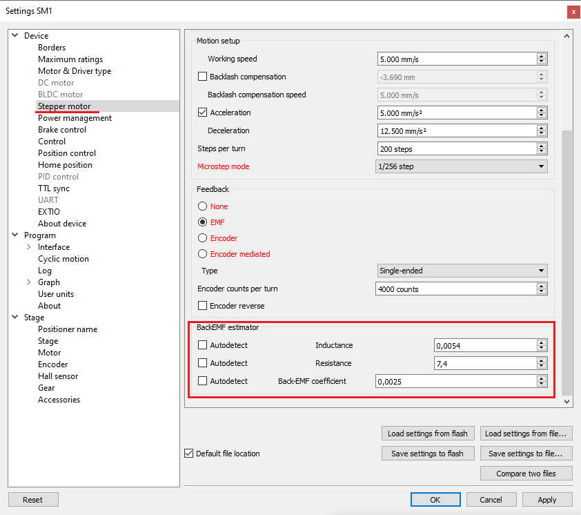
On the Stepper motor tab, you can additionally assign the following parameters:
- Resistance - winding resistance \(R\) Ω
- Inductance - winding inductance \(L\) H
- Back EMF coefficient - the flux linkage of the rotor \(\lambda_m\) Hm/A
- The value of all these parameters is saved in the engine profile.
Automatic detection of the back-EMF parameter works satisfactorily for most engines. However, assigning parameters via a profile provides greater stability of the algorithm.
The values \(R\) Ω and \(L\) H must be taken directly from the dataset.
The value of the rotor flux linkage \(\lambda_m\) Hm/a can be obtained as follows:
In the datasheet, the value of the motor’s Electromechanical coefficient \(K_m\) (torque constant, Hm/A) or the counter-EMF coefficient \(K_{emf}\) (backEMF constant, Vs), then
\(\lambda_m = \frac{4K}{n}\), where
\(K\) is the value of \(K_{emf}\) or \(K_{m}\), \(n\) - number of steps per revolution.
In the datasheet, the rated current \(i_n\) (nominal current, A) and the holding torque \(T_n\) (holding torque, Hm), then
\(\lambda_m = \frac{4T_n}{I_{n}n}\), where
\(n\) - number of steps per revolution.
4.2.9.4. The choice of PID coefficients for EMF
In field control mode, when the rotor position estimation is available,
the position is controlled using a standard PID controller.
Its coefficients ensure the stability of the engine in the area of high speeds.
The accuracy of working out a position by profile is determined by many factors:
- In hold mode - the ratio of the hold force to the interference force is the same as for all open-loop algorithms;
- At low speeds - the discrepancy between the actual position and the profile position should not exceed one step;
- At high speeds - the discrepancy can be several steps, due to transients, feedback coefficients, and the presence of external forces.
We suggest using a standard set of coefficients:
\(K_p = 3.6,\quad K_d = 0.028,\quad K_i = 38\)
- \(K_p\) increasing the coefficient increases the accuracy (reduces the \(\theta_e\) error), reduces the adjustment time;
- \(K_d\) increasing the coefficient increases the damping of the system and reduces vibrations. A low coefficient can cause instability because the \(K_d\) value is too small;
- \(K_i\) has little effect on accuracy in transient modes, but it reduces the steady error when moving at a constant speed and acceleration, and also allows you to compensate for constant external forces. In many applications, it can be accepted as null. If the value is too high, stability is lost.
4.2.9.4.1. Operation algorithm
The controller input is:
- \(\theta_r\) - desired rotor position (rad), the value of which is generated by the speed profile generator
- \(\omega_r\) - the desired angular speed of rotation of the rotor (rad/s), the value of which is generated by the speed profile generator
- \(\theta_{m}, \omega_{r}\) - rotor position (rad) and speed (rad/c) calculated using the rotor position estimation
Output: \(I_{qr}\) - the current value (À) that determines the torque generated by the engine: \(M = k_m I_{qr}\), where \(k_m\) is the Electromechanical coefficient (torque constant) of the engine
Parameters: \(K_p\), \(K_i\), \(K_d\) - feedback coefficients (values set in the “PID control” tab).
Control law:
1. Calculation of the control error:
\(\theta_e = \theta_{r} - \theta_{m}, \quad \omega_e = \omega_r - \omega_m\),
2. Calculation of current:
\(I_{qr} = K_p \theta_e + K_d \omega_e + K_i \int_0^t \theta_e d\tau\)
The controller is equipped with an anti-accumulation loop based on the conditional integration algorithm. The growth of the integral part stops if the current saturation occurs (\(|I_{qr}| > I_{max} and I_{qr}\cdot \theta_e < 0\))