4.2.13. PID-algorithm for BLDC engine control
4.2.13.1. PID-algorithm description
BLDC engine is controlled by the PID regulator, with the coordinate as the controlled parameter. The controlled coordinate changes according to motion settings and incoming commands to provide motion capability. We will call controller coordinate the running position. Output current is the control signal of the regulator. The control action is calculated according to the following formula:
\(U(t)\) - is the control action
\(E(t)\) - is difference between the running coordinate and the current motor coordinate
\(K_p, K_i, K_d\) - are proportional, integral and differential coefficients of the regulator. Regulator coefficients are set on PID settings page of the XiLab program or programmatically by calling set_pid_settings() function of the libximc library (see Programming guide).
The effects different PID components (Kp, Ki, Kd) have are same for BLDC and DC motors. See PID-algorithm for dc engine control.
4.2.13.2. PID regulator manual tuning
We provide a special XiLab extension for the manual adjustment of the PID regulator coefficients. The time dependence of the speed of the BLDC engine and the speed retention error is shown in a special window, see the screenshot below.
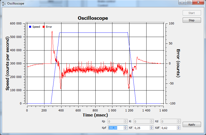
The PID regulator tuning window.
Stable position retention is a mandatory requirement for the correct operation of the motor/positioner. This means that after reaching the target setpoint, the position must be maintained without drift, without oscillations, and with minimal steady-state error. Only under these conditions will manual tuning of the PID regulator parameters provide correct results.
4.2.13.2.1. Steps to adjust the coefficients:
To tune the PID controller of a BLDC motor, the process should always start with the minimum rotation speed, so that the movements remain safe and controllable, and the motor does not enter into strong oscillations.
Step 1. Set the integral (\(K_if\)) and differential (\(K_df\)) coefficients to zero.
Start gradually increasing the proportional (\(K_pf\)) coefficient. It is recommended to begin with 0.1 and increase it by
a factor of 10 at each step (0.1 → 1 → 10 → …). At first, the motor may not respond to commands, but once the value reaches the proper range,
it will start reacting. If \(K_pf\) is too high, the response can become sharp and the motor may begin to vibrate or oscillate.
This means the coefficient is excessive and must be reduced until the rotation remains responsive but without unnecessary vibrations.
The result of tuning should be stable and smooth motion with quick response to changes, without shaking or jerks.
Step 2. The differential coefficient (\(K_df\)) should be tuned starting from 0.01, increasing by a factor of 5 at each step (0.01 → 0.05 → 0.1 → …).
The main purpose of \(K_df\) is to suppress oscillations. If vibrations decrease during acceleration and deceleration, the tuning is correct.
If the value is too high, the motor becomes sluggish and exhibits delayed response.
The result of tuning should be confident and smooth motion without oscillations during speed changes.
Step 3. The integral coefficient (\(K_if\)) should be tuned starting from 0.001, increasing by a factor of 5 at each step (0.001 → 0.005 → 0.01 → …).
The purpose of \(K_if\) is to eliminate the residual error, ensuring that the motor precisely maintains the target speed or position without noticeable offset.
If \(K_if\) is too high, the motor will begin to oscillate and may enter self-oscillation.
The result of tuning should be accurate position holding without drift and without loss of stability.
4.2.13.2.2. PID tuning for increased mass:
First, you need to evaluate the PID coefficients. Given the structure of the managed system, they can be calculated from simplified formulas. For this, the parameters from the documentation for the appropriate motor and stage are used.
- \(K_m\) - electromechanical motor coefficient [H / A] (the torque generated by the current strength is 1 A). Can be calculated as the ratio \(K_m = \frac{F_n}{I_n}\), where \(F_n\) is the nominal (maximum) force generated by the motor, \(I_n\) is the rated (maximum) current strength.
- \(M\) - weight of load (kg).
- \(\sigma = \frac{M}{K_m}\).
- Example for stage 8MTL1301-170:
Uploading a profile for this stage. From it we will find out the default PID coefficient:
Kp 200 000, Ki 250, Kd 625.The km coefficient was calculated using the formula above, for this stage it is equal to 12.9.
According to the formula, find the PID coefficients for a weight of 4.7 kg.
\(\sigma = 4.7 / 12.9 = 0,3643\).The resulting value \(\sigma\) is multiplied by the available PID coefficients from the profile, and we get:
- \(200 000 \cdot 0,3643 = 72 860\);
- \(250 \cdot 0,3643 = 91,075\), round this value to 91;
- \(625 \cdot 0,3643 = 227,6875\), round this value to 228.
Set the coefficients calculated by formulas, click Apply. Click the Zero button on the main XiLab window. Set 0 to the Move to field, send the command. The engine should stop. Try to move the position manually, make sure that the response is correct - the engine tries to return to zero position (the encoder reverse is set correctly).
Set a small speed in the motion settings, click Apply. Start moving in the main window. The differential coefficient (Kdf) should be increased if there are vibrations and disruptions.
If the vibrations have audio frequencies (the stage emits a loud sound when driving), it may be necessary to reduce the Kd coefficient or all the coefficients proportionally.
The integral coefficient (Kif) is responsible for getting into the target position, it is convenient to use the command Shift on for testing.
To fine-tune the coefficients use the Oscilloscope window where the speed retention error is displayed for used motion parameters.
After the coefficients are adjusted, they need to be proportionally increased/decreased, this corresponds to an increase/decrease in mass, response to the impact becomes more/less powerful, sudden stops will not lead to disruption of movement.