5.3.2. Motion range and limit switches
In the Application settings Device -> Borders
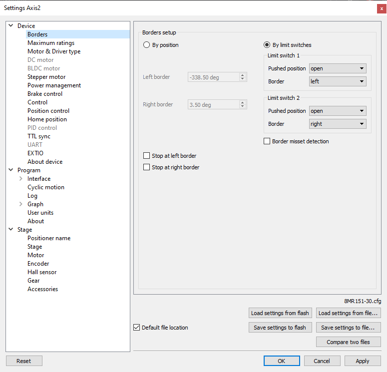
Motion range and limit switches settings window
Borders setup parameter group contains borders and limit switches parameters. These parameters are used to keep the stage in the permissible physical movement limits or motion range limit in accordance with the user requirements. Borders can be set either by position (internal controller step counter) or by limit switches located in the stage terminal points.
If there are no hardware limit switches for the motion range but the stage requires such limitation, the programmable limit switches can be used. To do this, the limit switches should be switched to By position and specify the Left border and Right border values, which correspond to the left and right edge respectively. The left and right border fields are used (the value of Right border should be higher than Left border). In this mode, the left virtual limit switch is active if the actual position is less than the left border value and the right one is active if the actual position is greater than the right border value. The operation time is about one millisecond.
Warning
The programmable motion range limitation is reliable only if there is no direct setting of the new position by ZERO or SPOS commands, or if there is no steps loss or encoder malfunction if it is used for positioning, or if there is no frequent power-cut during the rotation. If any of these problems appears, the programmable range should be re-adjusted. The appropriate reference sensor allows the automatic re-adjustment using the automatic Home position calibration feature.
To set the borders by the limit switches select By limit switches and set up both Limit switch 1 and Limit switch 2.
Pushed position - sets the limit switch condition when it is reached: open or closed.
Border - sets the limit switch position: on the left or on the right of the stage working range.
Check the Stop at left border and / or Stop at right border for a forced stop of motor when the border is reached. In this case the controller will ignore any commands of movement towards the limit switch if the corresponding limit switch has already been reached.
When the border position is reached the corresponding indicator flashes in the main application window.
If the Border misset detection flag is checked, the engine stops upon reaching of each border. This setting is required to prevent engine damage if limit switches appear to be potentially incorrectly configured. Read more about controller operation in this mode in the limit switches location on stages.